
Circuit Diagram for Mini Emergency Lamp

The circuit for the mini emergency lamp is designed to be simple yet effective for providing illumination during power outages. The primary components include a 1-watt white LED, a rechargeable battery, a charging circuit, a power switch, and a control circuit that detects power failure.
When the main power supply is operational, the charging circuit ensures that the rechargeable battery is kept at full charge. This can be achieved using a small solar panel or a conventional AC-DC adapter, depending on the intended use and design preferences. The charging circuit typically consists of a diode to prevent backflow of current, a voltage regulator to maintain the battery voltage within safe limits, and a current limiting resistor to protect the LED from excessive current.
Upon detection of a power failure, the control circuit activates, switching the LED on to provide light. This can be accomplished through a relay or a MOSFET that connects the LED to the battery. The LED is chosen for its efficiency and long life, making it suitable for emergency lighting applications. The output of the LED should be connected through a current-limiting resistor to ensure that it operates within its rated specifications.
To enhance usability, the lamp may also include features such as an indicator LED to show when the unit is charging or fully charged, as well as a switch to allow the user to turn the lamp on or off manually. Additional components may include a fuse for overcurrent protection, ensuring the safety and reliability of the device during operation.
Overall, the mini emergency lamp circuit is a practical solution for providing essential lighting in times of need, with a focus on simplicity, efficiency, and reliability.Circuit Diagram for Mini Emergency Lamp. This Mini Emergency Lamp turns on when power fails to give cool white light in the room. It uses 1 watt White LED to provide sufficient light in the room 🔗 External reference
Related Circuits
This sound frequency meter circuit is simple to build and can be constructed in a portable format. It can measure frequencies with a minimum level of 10 mV. The sound frequency meter circuit is designed to provide an effective and...
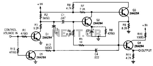
A DC control voltage varies the effective resistance in the feedback network consisting of capacitors C4, C3, C1 and resistors R12, R3. Additionally, Q2 and Q3 serve as the oscillator transistors. The circuit operates by utilizing a DC control voltage...
A clock-and-data recovery (CDR) circuit is utilized to recover the clock from a transmitted data stream and re-time that data with the recovered clock. These circuits are generally positioned at the front-end of receiver chips to extract the clock...
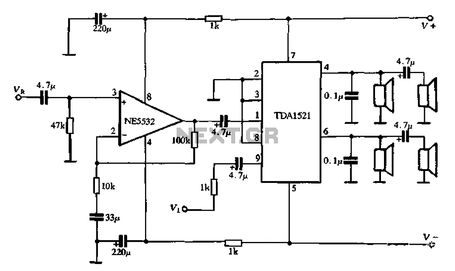
Active speaker with amplifier circuit TDA1521 and NE5532, featuring dual-channel input and dual-channel output. The active speaker circuit utilizes the TDA1521 integrated circuit, which serves as the power amplifier. This IC is designed for high-efficiency amplification, providing a robust output suitable...
The circuit was designed to illustrate the use of a tone control circuit, which adjusts audio signals before they are sent to any output device. The tone control circuit serves as an essential component in audio processing systems, allowing for...

A DC brush motor driver circuit diagram utilizing the MC33035 chip is presented, illustrating a typical configuration for driving a straight DC brush motor. The circuit incorporates a field-effect transistor (FET) bridge driver setup. When transistor VT3 is activated,...