
A voice-activated lights control circuit

The circuit operates as a 22W power supply utilizing an RC buck converter topology, which efficiently steps down voltage while maintaining a regulated output. The rectification process is achieved through a normally closed (n.c.) configuration, followed by filtering to smooth out the rectified output, ensuring a stable 3V DC supply. This regulated output is essential for powering components labeled as U, V2, and the microphone (MIC).
The microphone (MI) plays a crucial role in the system by converting incoming acoustic signals into corresponding electrical signals. When an audio signal is detected, it triggers the discharge tube (T), which acts as a switch to control the flow of current. The output from the discharge tube is then coupled to a two-way silicon controlled rectifier (SCR), which is responsible for controlling the timing of the electrical pulses sent to the load.
The SCR is triggered by the audio signal, allowing it to conduct and control the discharge of energy to the connected load. This results in a visually appealing light effect, where the intensity and frequency of the light can vary based on the characteristics of the incoming audio signal. The entire system is designed to respond dynamically to sound, creating an interactive experience that links audio input with visual output.22W by Ct and R, RC Buck, rectified by n. c, filtering. vz 3V DC regulated output power, before U, V2 and MIC power supply. When the audio signal to the beam, the microphone MI C acoustic energy into electrical energy, and then the general discharge tube T and after coupling, can be entrusted to two-way silicon v dispatch a trigger voltage control, use audio to control thyristor conduction and cut u :, D generated so lights sparkle.
Related Circuits
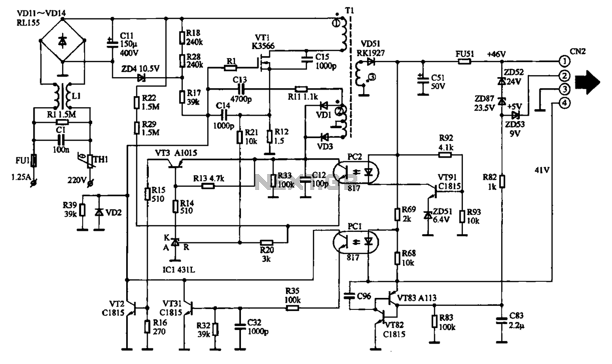
The EPSON PHOTO 830U printer power circuit illustrates the power supply circuit for the EPSON PHOTO 830U printer, which operates as a switching power supply. During normal operation, the power supply input socket receives a 220V AC supply to...
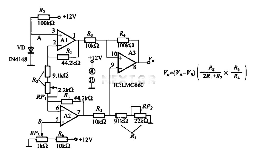
A diode IN4148 temperature circuit is presented. The circuit operates within a temperature range of -25 to 125 degrees Celsius, with an accuracy of 0.5. The core components of the operational amplifier circuit consist of four LMC660 amplifiers. It...
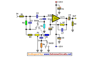
Simple add-on module, Switchable "Control-flat" option. In order to obtain good audio reproduction at different listening levels, a different tone control... The described module is a straightforward add-on designed to enhance audio reproduction across various listening levels. The "Control-flat" option...
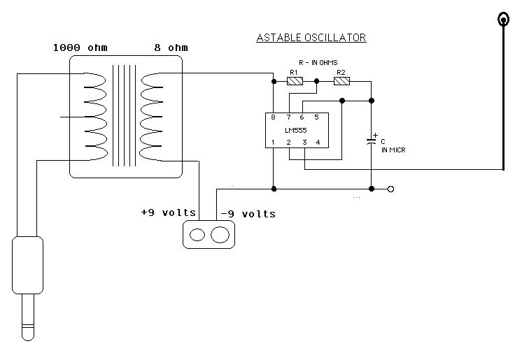
Two ICM7555 CMOS 555 timers are available, and there is an inquiry about effective AM radio transmitter circuits that utilize one or both of these timers. The ICM7555 is a low-power CMOS version of the classic 555 timer, which can...
AN79 Linear Technology AN79 modifies methods presented in AN74, allowing for the verification of 30 nanosecond amplifier settling times with 0.1% resolution. The sampling-based technique used is detailed, and results are presented. Appendices cover oscilloscope overdrive issues, the construction...
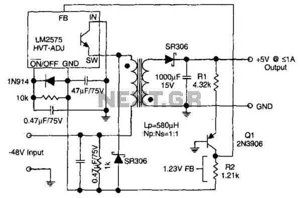
The circuit supplies 1 A at +5 V from the -48 V supply commonly used in telephone equipment. More: The National Semiconductor LM2575 is a simple switching regulator. The circuit utilizes the National Semiconductor LM2575, which is a step-down (buck)...