
555 Am TransmitterCircuits

The ICM7555 is a low-power CMOS version of the classic 555 timer, which can be configured in various modes including astable, monostable, and bistable operations. In the context of an AM radio transmitter, the 555 timer can be used to generate a modulated signal suitable for transmission.
A typical AM radio transmitter circuit using a 555 timer consists of several key components: the 555 timer itself, an oscillator circuit, a modulating signal input (which could be audio), and an output stage that includes an RF amplifier and an antenna.
For a simple AM transmitter using a single ICM7555, the timer can be configured in astable mode to generate a carrier frequency. The frequency can be set by selecting appropriate resistor and capacitor values connected to the 555 timer. The output from the timer can be fed into a transistor amplifier stage, which increases the power of the signal to drive an antenna for transmission.
If utilizing two ICM7555 timers, one can serve as the modulator while the other functions as the oscillator. The first timer generates the carrier wave, and the second timer can modulate this signal with an audio input. The modulated output can then be amplified and transmitted via an antenna.
It is essential to ensure that the output frequency falls within the AM radio band (typically 530 kHz to 1700 kHz) for proper reception. The circuit should also include appropriate filtering to eliminate unwanted harmonics and ensure a clean signal is transmitted.
When designing the circuit, attention must be paid to power supply decoupling, component ratings, and antenna matching to optimize performance and ensure compliance with local regulations regarding radio frequency transmissions.I have two ICM7555 CMOS 555 timers, and I was wondering if anyone has any good am radio transmitter circuits that incorporate two (or one!) 555 timers.. 🔗 External reference
Related Circuits
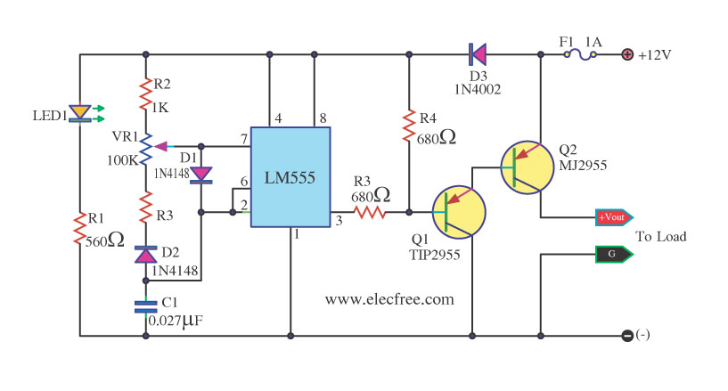
This circuit is a DC dimmer circuit that utilizes the LM555 integrated circuit configured as an astable multivibrator. It is capable of adjusting the duty cycle by fine-tuning variable resistors VR1 and VR2. The DC dimmer circuit employs the LM555...
This circuit illustrates a Wiper Speed Control Circuit Diagram. The sweeping rate of the wiper can vary from once per second to once every ten seconds. The Wiper Speed Control Circuit is designed to regulate the speed of windshield wipers...
The circuit is based on the IC1 that is 555, for the creation of alternate flashes from the two led D1-2, that can be also different colour. The frequency of alternation can be regulated from the trimmer R3 and...

This is a simple smoke alarm circuit using a timer IC, the NE555. The circuit operates by illuminating a Light Dependent Resistor (LDR) with a lamp. When smoke obscures the light from the lamp, the resistance of the LDR...
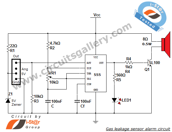
This article discusses a home security alarm circuit designed to detect LPG gas leakage. The circuit utilizes a gas sensor module, SEN 1327, which incorporates a QM 6 gas sensor. The output signal from this gas sensor module is...
The schematic shown below is a 555 timer circuit. The NE555 is a well-known integrated circuit that comes in an 8-pin dual in-line package (DIP). There is a vast array of circuits utilizing the 555 IC, which contributes to...