
A3952S stepper motor controller circuit design

The A3952S stepper motor controller is an integrated circuit designed to drive stepper motors efficiently and effectively. This device is particularly advantageous for applications requiring precise control of motor position and speed. The controller's ability to handle continuous output currents of up to 2 A makes it suitable for a variety of stepper motors, from small to medium-sized applications.
The internal fixed off-time PWM current control circuitry is a key feature, as it allows the user to set a maximum load current, which is crucial for protecting the motor and the driver from overheating and damage. The use of the MODE terminal provides flexibility in operation, enabling the selection of different modes for microstepping, which enhances the smoothness of motor operation and reduces vibrations.
In applications where the load current is subject to rapid changes, the implementation of slow-decay mode is beneficial. This mode helps in reducing the switching losses that occur during the operation of the motor, thereby improving overall efficiency. Additionally, the reduction of iron losses in the motor contributes to better performance and longevity of the motor.
For applications that demand high performance under heavy loads or continuous duty cycles, the thermal management of the A3952S is critical. By adding external diodes in parallel with the internal diodes, heat dissipation can be significantly improved. This is particularly important in high-current scenarios where excessive heat can lead to failure of the device. The recommendation to use only the top-side diodes for slow-decay applications simplifies the design while ensuring adequate thermal performance. Conversely, for fast-decay PWM applications, the inclusion of all four external diodes is essential to maintain optimal thermal conditions and prevent junction temperature from exceeding safe limits.
In summary, the A3952S stepper motor controller is a versatile and efficient solution for driving stepper motors in various electronic applications, providing features that enhance performance, efficiency, and thermal management.Using the A3952S stepper motor controller designed by Allegro MicroSystems can be designed a very simple and useful motor driver circuit that can be used in many electronic applications. A3952S stepper motor controller is capable of continuous output currents up to 2 A and operating voltages range up to 50 V.
Internal fixed off-time PWM current-c ontrol circuitry can be used to regulate the maximum load current to a desired value. The MODE terminal can be used to optimize the performance of the device in microstepping / sinusoidal stepper motor drive applications. When the average load current is increasing, slow-decay mode is used to limit the switching losses in the device and iron losses in the motor.
The thermal performance in applications with high load currents and/or high duty cycles can be improved by adding external diodes in parallel with the internal diodes. In internal PWM slow-decay applications, only the two top-side (flyback) diodes need be added. For internal fast-decay PWM, or external PHASE or ENABLE input PWM applications, all four external diodes should be added for maximum junction temperature reduction.
We aim to transmit more information by carrying articles. Please send us an E-mail to wanghuali@hqew. net within 15 days if we are involved in the problems of article content, copyright or other problems. We will delete it soon. 🔗 External reference
Related Circuits
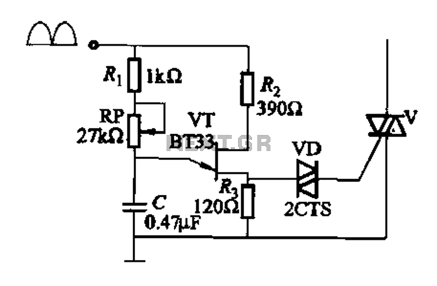
Figure 16-29 (a) illustrates the trigger output through a resistor R2, while Figure 16-29 (b) depicts the integration of a programmable unidirectional transistor (PUT) trigger circuit. The adjustable potentiometer RP can modify the conduction angle of the TRIAC to...
Assistance is needed for the design of a timing circuit intended to activate a spark plug every 10 or 20 revolutions of a shaft. The timing circuit for firing a spark plug at specified intervals can be designed using a...
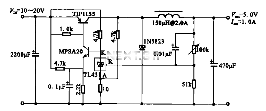
The 5V regulator circuit is designed to convert a DC input voltage ranging from 10V to 20V into a stable 5V output. This circuit features low power consumption and high efficiency. The 5V regulator circuit typically employs a linear voltage...
A constant speed motor control can be achieved using closed-loop (servo) control. A constant speed motor maintains a steady speed regardless of variations in load. In a closed-loop control system, feedback is utilized to compare the actual speed of the...
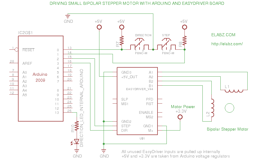
A video and the circuit with schematics for connecting and controlling the world's smallest linear actuator based on a bipolar stepper motor from a Blu-ray drive. The project involves the design and implementation of a circuit to control a linear...
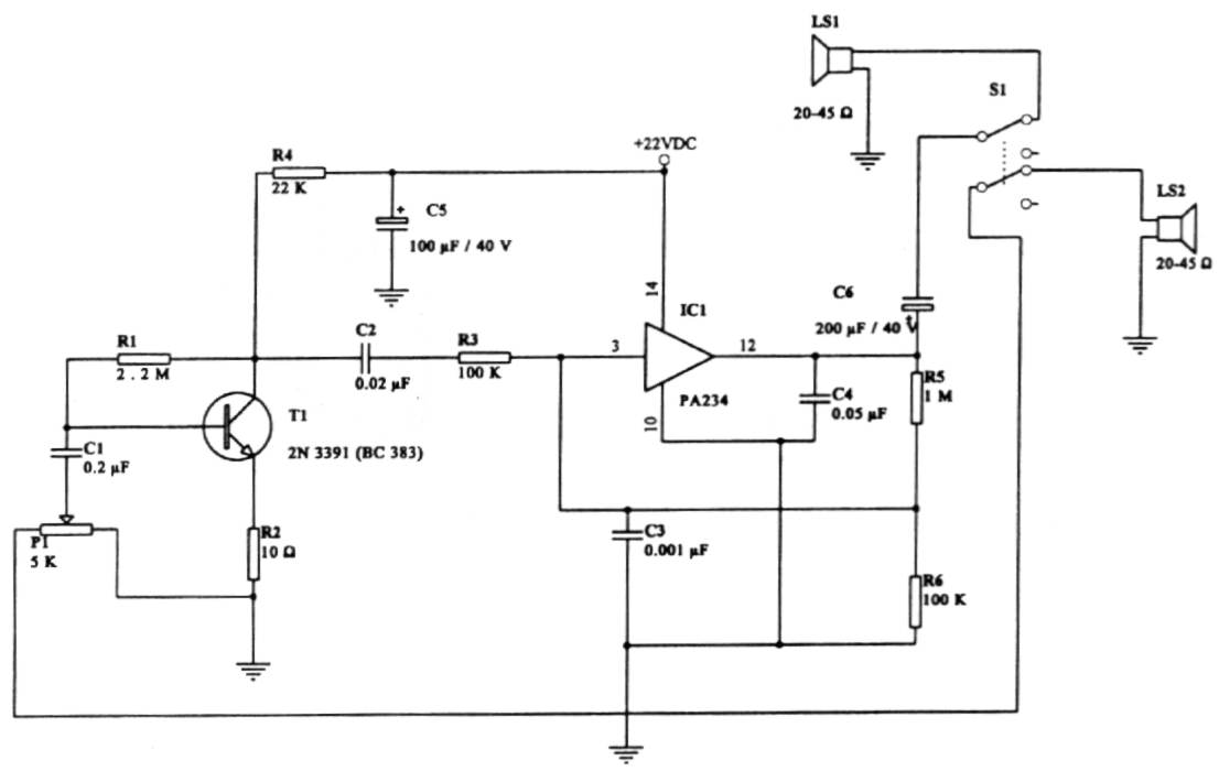
This intercom circuit is versatile and can be utilized in various applications. It operates at 22V, although it may function at a lower voltage (experimental testing is suggested). The circuit utilizes a loudspeaker with an impedance of 20-45 Ohms...