
timing circuit

The timing circuit for firing a spark plug at specified intervals can be designed using a combination of a rotary encoder, a microcontroller, and a driver circuit. The rotary encoder will provide feedback on the shaft's rotation, generating a pulse for each complete revolution. This pulse can be processed by a microcontroller, which is programmed to count the pulses and determine when to activate the spark plug.
The microcontroller can be configured to trigger an output pin after counting either 10 or 20 pulses, depending on the desired timing. The output from the microcontroller can then be connected to a transistor or a relay, which will act as a driver circuit to handle the higher current required to ignite the spark plug.
The schematic would include the following components:
1. **Rotary Encoder**: This device will convert the mechanical rotation of the shaft into electrical signals. It typically outputs a series of pulses corresponding to each revolution.
2. **Microcontroller**: A suitable microcontroller (e.g., Arduino, PIC, or STM32) will be programmed to count the pulses from the rotary encoder. It will also control the timing of the spark plug firing.
3. **Driver Circuit**: A transistor (NPN or MOSFET) or a relay will be used to switch the high voltage required for the spark plug. The microcontroller output pin will connect to the base/gate of the transistor/relay.
4. **Power Supply**: A power supply capable of providing the necessary voltage and current for both the microcontroller and the spark plug circuit.
The overall circuit should also include necessary protective components such as diodes to prevent back EMF from damaging the microcontroller and capacitors for noise filtering. Proper layout and grounding techniques should be employed to ensure reliable operation and minimize interference.
This design will allow for precise control over the timing of the spark plug firing, ensuring optimal performance for the intended application.I am hoping to get some help on a timing circuit I need to build. I need to have a spark plug fire every 10 or 20 revolutions that a shaft.. 🔗 External reference
Related Circuits

A high-input-resistance operational amplifier (op-amp), a bridge rectifier, a microammeter, and several discrete components are necessary to implement this versatile circuit. This circuit can measure DC, AC RMS, AC peak, or AC peak-to-peak voltage by simply altering the resistor...
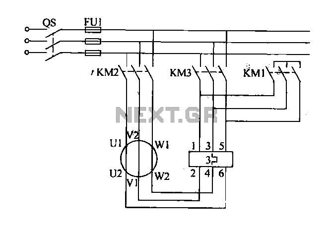
Traditional control methods for fan power equipment involve manual or relay control, which often leads to issues of poor reliability and flexibility. For instance, when the motor capacity is large, the startup process can be prolonged, resulting in high...

The SOS Alarm centralized control circuit is designed for use in calling a hospital bed and can also serve as an anti-theft alarm in multi-storey buildings, dormitories, warehouses, and similar locations. The circuit, as depicted in Figure 13-64, features...
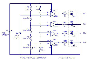
This circuit is a practical device that, when installed in a vehicle, displays the voltage of the car battery using an LED dot display. The meter circuit utilizes four comparators formed from a quad op-amp, specifically the LM324. The...
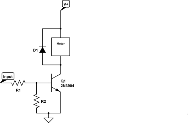
Control a small 5V motor using an external power supply by triggering a transistor with an Arduino. The transistor in use is an NPN type, specifically the 2N3904. To control a small 5V motor using an Arduino and an NPN...
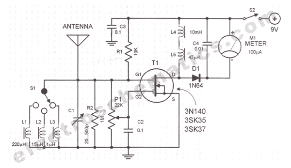
Comprehensive information regarding the RF Field Strength Meter Circuit is available. Users can learn about and download the RF Field Strength Meter Circuit online. The RF Field Strength Meter Circuit is designed to measure the strength of radio frequency (RF)...