
AC-coupled differential amplifier PGA202

The PGA202 circuit operates as a differential amplifier designed for high-performance applications, particularly in audio and signal processing. The AC coupling is achieved using the two 1 µF capacitors, which effectively block any DC offset present in the input signal while allowing AC signals to pass through. This is crucial in maintaining signal integrity and preventing saturation of the amplifier.
The two 1 MΩ resistors form a voltage divider with the capacitors, setting the input impedance of the circuit and determining the low-frequency response. The calculated cutoff frequency of approximately 0.16 Hz indicates that signals below this frequency will be attenuated, while higher frequency signals will be amplified. This characteristic is essential for filtering out unwanted low-frequency noise, ensuring that only the desired AC signals are processed by the amplifier.
In practical applications, the output of the PGA202 can be connected to further signal processing stages, such as additional amplification or filtering circuits. The design is particularly suitable for audio applications, where maintaining the fidelity of the signal is paramount. The use of high-value resistors and capacitors allows for a compact design while achieving the necessary performance specifications. As shown in FIG PGA202 constituted by AC-coupled differential amplifier. The circuit at the input PGA202 plus two 1 F capacitors and two 1M resistor composition frequency 0.16H z above Qualcomm AC coupling circuit, after the AC signal input differential amplifier PGA202 output.
Related Circuits
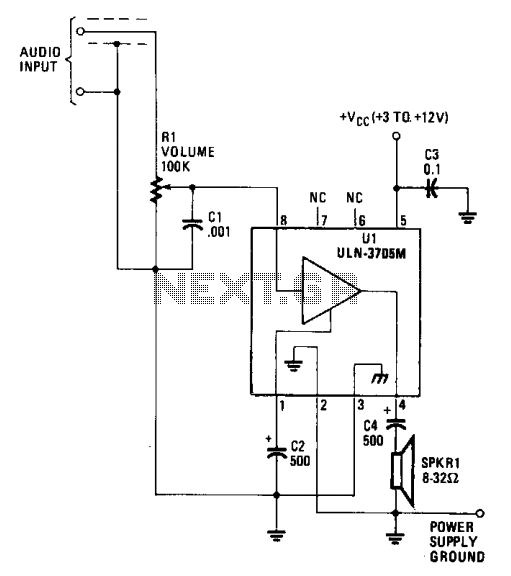
The amplifier functions with supply voltages up to 12 volts and can operate at lower voltages as low as 1.8 volts while maintaining acceptable distortion levels, albeit with reduced volume. Its power requirements make it suitable for applications powered...

This circuit features a high-input-impedance AC resistance of 880 kΩ and a gain of 10, utilizing an operational amplifier for a piezoelectric transducer. The described circuit is designed to interface with a piezoelectric transducer, which generates an AC voltage in...
This mini audio amplifier will test the audio stages in amplifiers such as the front end of FM bugs. You can also use it on lots of our other projects as well as the output stages of radios. It...
A 30W Class AB power amplifier circuit diagram utilizes a power transistor. To set up the amplifier, adjust the variable resistor R1 to its maximum value and R12 to zero. After completing this setup, activate the amplifier. Adjust R1...
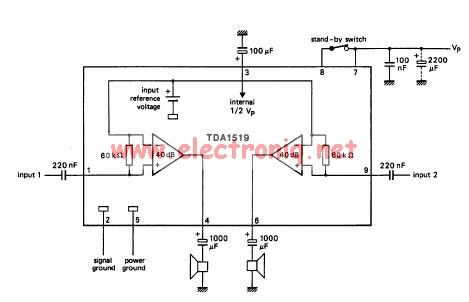
The TDA1519 circuit can deliver 2x6 watts of output power. The TDA1519 is an integrated class-B dual output amplifier housed in a 9-lead single in-line (SIL) plastic medium power package, primarily developed for car radio applications. The TDA1519 amplifier is...
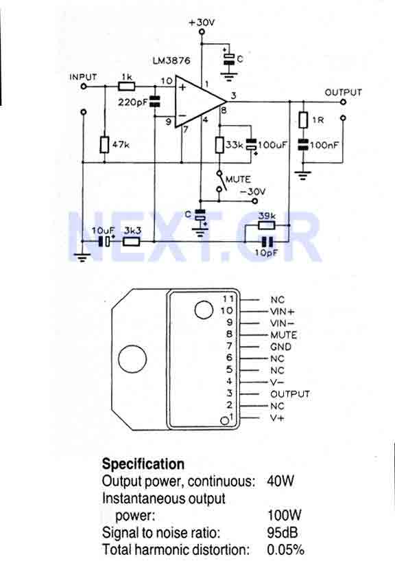
This Circuit is based on the LM3876. A 11-pin plastic package IC with high performance audio power amplifier, an output mute function which can be used to eliminate switch-on and switch-off "thumps" to the loudspeaker load. It is capable...