
Transducer amplifier

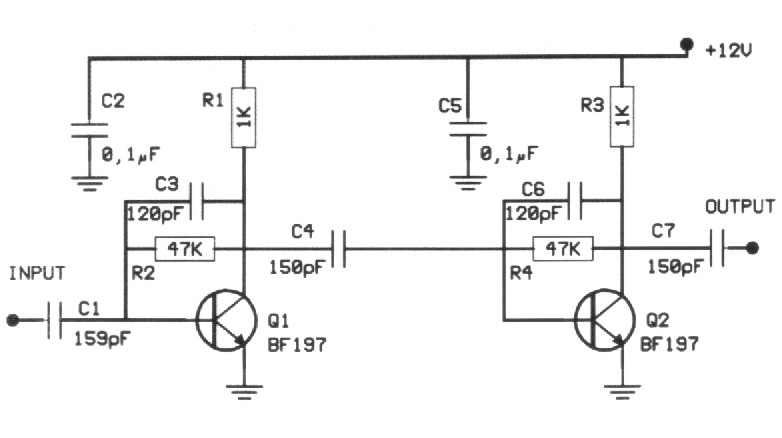
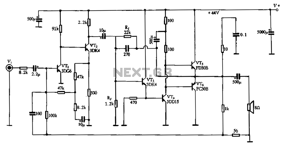
The described circuit is designed to interface with a piezoelectric transducer, which generates an AC voltage in response to mechanical stress. The high-input impedance of 880 kΩ ensures minimal loading on the transducer, preserving the integrity of the signal generated. This characteristic is crucial when dealing with piezoelectric devices, as they typically produce low-level signals that can be easily affected by impedance mismatches.
The operational amplifier (op-amp) configuration employed in this circuit provides a gain of 10, amplifying the voltage signal from the piezoelectric transducer to a more usable level. The gain can be set using feedback resistors, which are critical in determining the overall performance of the amplifier. In this case, the feedback network is designed to achieve the desired gain while maintaining stability and linearity.
The circuit's design may also include additional components such as capacitors for AC coupling, which blocks any DC offset that may be present in the signal, and resistors to set the input and output impedance levels appropriately. The choice of op-amp is also vital, as it should have low noise characteristics and a suitable bandwidth to accommodate the frequencies produced by the piezoelectric transducer.
Overall, this circuit effectively amplifies the small signals generated by piezoelectric transducers, making it suitable for various applications, including sensors, actuators, and other devices that rely on mechanical-to-electrical signal conversion. Proper attention to component selection and circuit layout will enhance performance and reliability in practical implementations.This circuit is high-input-impedance ac resistance is 880 K, and a gain of 10 is ob-amplifier for a piezoelectric transducer Input tained.
Related Circuits
An ideal solution for making a good, low-cost power amplifier. It's an ideal solution for creating a home cinema system. The preamplifier and the driver are supported in an operational amplifier [IC1]. The voltage drop in resistors R5 and...
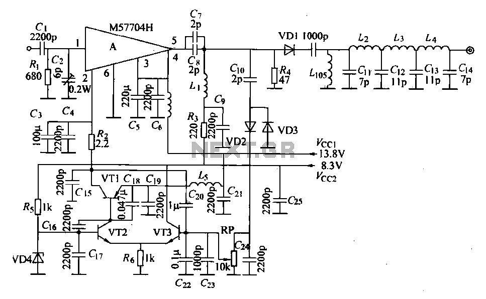
The FM radio transmitter is a high-frequency amplifier circuit that utilizes the Mitsubishi frequency set, specifically the M57704H discharge path. It operates within the frequency range of 457-458 MHz and has a transmission power of 5 watts. As illustrated...
The preamplifier provides a gain of 20dB across the VHF range and can extend its functionality up to 500MHz. This high-frequency RF amplifier is constructed using distinguishable materials, enhancing the signal based on its frequency. If the input signal...
The LM3886 is an improved version of the LM3875. Key features of the LM3886 include a maximum output power of 68W RMS and 108W peak, with a total harmonic distortion (THD) of 0.03% at 60W. The LM3886 is a high-performance...
The lower FET operates in common source mode, while the upper FET operates in common gate mode, achieving full high-frequency gain. The bottom FET is tunable, allowing for peak adjustment for a particular station. Coil details follow: The described circuit...
The circuit schematic depicted in Figure 2-3 illustrates a twin direct-coupled input amplifier stage composed of components OV, RLR, and VT2. The emitter of VT2 is connected to the base of VT3, utilizing local feedback to stabilize its DC...