
AC Current Monitors

The circuit is designed to provide a versatile solution for monitoring high-current electrical loads. The sensor component, which is critical for the operation, must be strategically placed in contact with the feeder cable to detect current flow effectively. The use of an inductor allows for the detection of alternating current (AC) without direct electrical contact, thus ensuring safety and reliability.
In the basic version of the circuit, the differential amplifier (IC1) amplifies the small AC voltage induced by the current flowing through the feeder line. This amplified signal is sufficient to activate the LED (D1), indicating that power is being drawn by the load.
The second version introduces a relay (Q1) that activates when the current surpasses a predetermined threshold, which is adjustable via the trimmer (R6). This feature allows for the integration of additional devices such as alarms or indicator lamps, enhancing the circuit's functionality. The dual op-amp configuration (IC1A and IC1B) provides the necessary signal processing to ensure accurate current detection and relay activation.
The third version expands the circuit's capabilities further by incorporating multiple comparators (IC1B, C, and D) configured to switch on additional LEDs (D5, D6, D7) based on varying current thresholds (1 kW, 2 kW, and 3 kW). This allows users to visually monitor the power consumption of connected devices, providing a clear indication of load status at different power levels.
Overall, this circuit design is highly adaptable, allowing for the monitoring of a wide range of high-power appliances. Proper placement of the inductor is crucial for optimal performance, as incorrect positioning can lead to signal cancellation, rendering the circuit ineffective. The careful selection of components and configuration ensures reliable operation and accurate monitoring of electrical loads.This circuit was designed on request, to remotely monitor when a couple of electric heaters have been left on. Its sensor must be placed in contact with the feeder to be able to monitor when the power cable is drawing current, thus causing the circuit to switch-on a LED.
Any type of high-current load or group of loads can be monitored, e. g. heater s, motors, washing machines, dish-washers, electric ovens etc. , provided they dissipate a power comprised at least in the 0. 5 - 1KW range. This design features three versions. The basic one illuminates a LED when the load is on. The second version drives a Relay when a pre-set current value flows into the power cable. The third version switches-on D7 when the load power is about 1KW, D6 when the load power is about 2KW and D5 when the load power is about 3KW. The basic circuit is shown top left in the drawing and must be used in all three versions. IC1 acts as a differential amplifier having a gain of 220. The small AC voltage picked-up by L1 is therefore amplified to a value capable of driving the LED D1.
The second version is drawn bottom left, must be connected to the basic circuit and uses a dual op-amp, therefore IC1 will be labeled IC1A and its pin connection varies slightly. IC1B acts as a voltage comparator and its threshold voltage can be precisely set by means of trimmer R6.
Q1 is the Relay driver and D2 illuminates when the Relay is on. You can use the Relay contacts to drive an alarm or a lamp when the AC load exceeds a pre-set value, e. g. 2KW. The third version is shown to the right of the drawing, must be connected to the basic circuit and uses a quad op-amp, therefore IC1 will be labeled IC1A and its pin connection varies slightly.
IC1B, C and D are wired as comparators. They switch on and off the LEDs, referring to voltages at their non-inverting inputs set by the voltage divider resistor chain R11-R14. The sensitivity will be doubled if the inductor is placed tightly between the two wires as shown in the diagram, top left.
On the contrary, do not place the inductor against paired wires as the signal tends to cancel and the circuit will not work. 🔗 External reference
Related Circuits
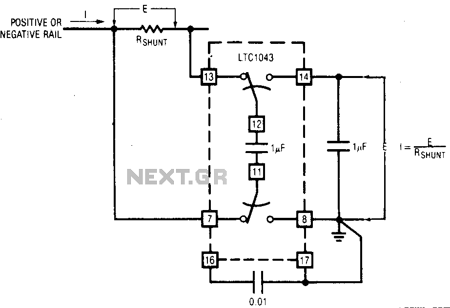
The LTC1043 can be induced through any of its current shunt supply rails. Many cells and solar system applications have this feature. If the reference point is grounded, the voltage output of an unloaded amplifier is minimal, allowing the...
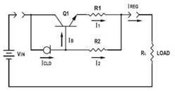
This application datasheet article includes sections that discuss the practical current booster circuit technique, which involves a conventional circuit using a Constant Current Load (CLD) and a current boosting circuit technique. It covers the analysis of the booster circuit...
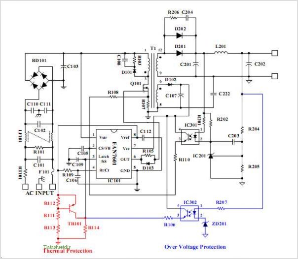
The UTC H1277 is a semiconductor integrated Hall Effect Sensor integrated circuit (IC). It is designed for applications where the accurate tracking of small magnetic flux density changes is critical. The H1277 can be utilized in various applications, including...
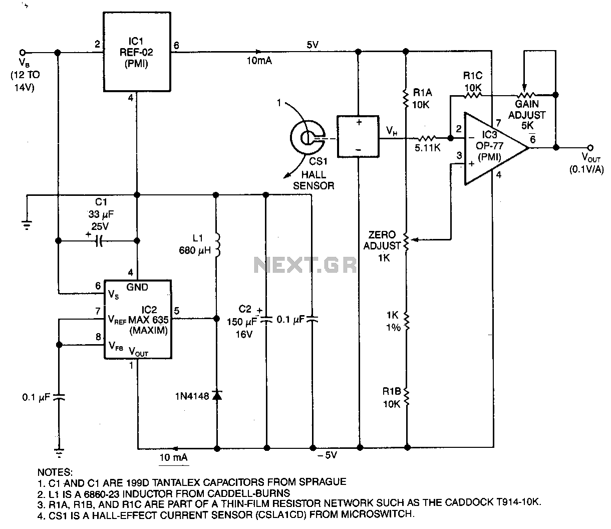
This circuit utilizes a Hall-effect sensor, comprised of an integrated circuit (IC) positioned within a small gap of a flux-collector toroid, to measure current in the range of 0 to 40 A. The current-carrying wire is threaded through the...
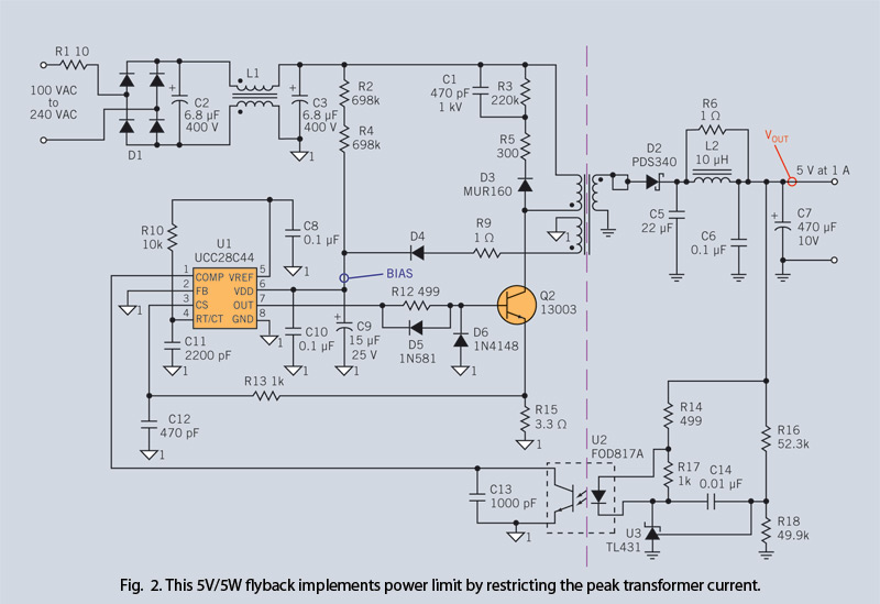
Through simple circuit modifications, designers can use peak current limiting to produce a constant current source. A constant current source is an essential component in various electronic applications, providing a steady output current regardless of load fluctuations or variations in...
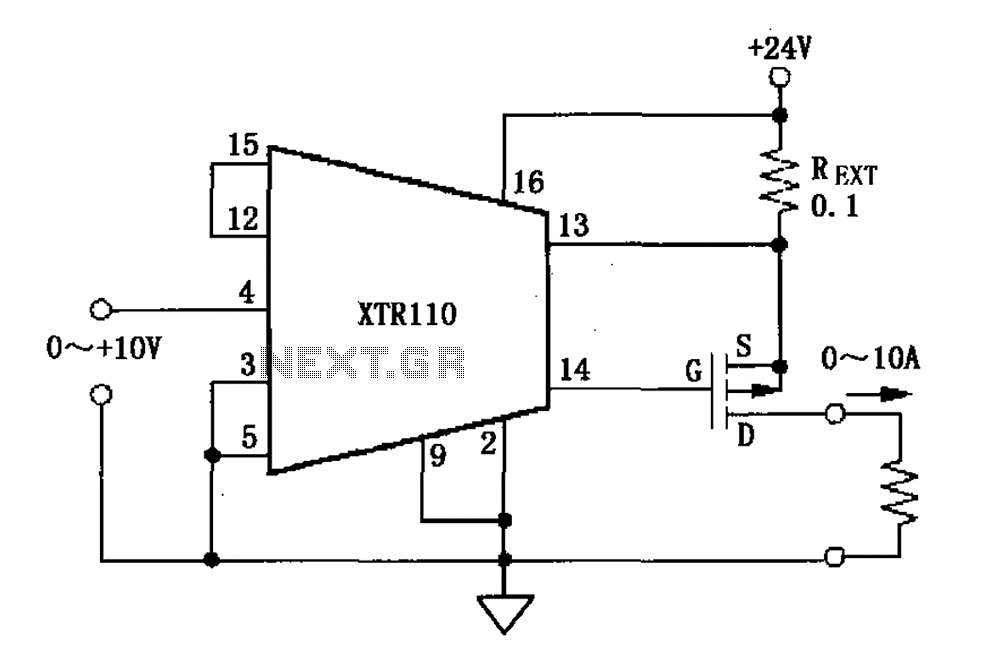
When the output current exceeds 40mA, the XTR110 requires the use of an external resistor (REXT) instead of the internal 50-ohm resistor (R9). REXT should be connected between pin 13 and pin 1. The value of REXT is determined...