
AC-DC Microammeter Circuit

The circuit is designed to facilitate precise measurements of both DC and AC microamperes using an analog meter. The core of the design involves a sensitive operational amplifier configured to amplify the current signal, which can then be displayed on a calibrated analog meter.
For DC measurements, a shunt resistor is employed to convert the current to a measurable voltage drop. The operational amplifier takes this voltage and amplifies it to a level suitable for the analog meter, ensuring that even small currents can be accurately measured. The configuration allows for a wide range of sensitivity, making it suitable for delicate applications.
To extend the functionality to AC microamperes, the circuit incorporates a rectifier stage. This stage converts the AC signal into a corresponding DC voltage that can be processed by the operational amplifier. A capacitor is included to filter out high-frequency noise, ensuring that only the desired signal is amplified.
The analog meter is calibrated to read both AC and DC measurements, allowing for easy interpretation of results. Additionally, the circuit may include a switch that allows the user to toggle between AC and DC measurement modes, enhancing versatility.
Overall, this circuit design offers a robust solution for measuring low-level currents in both AC and DC formats, making it an invaluable tool in various electronic applications.Here s a design circuit that is used to active circuitry and an analog meter to make sensitive DC current measurements. A reader subsequently asked if it could measure AC microamperes and that is what spawned the idea. This is the figure of the circu .. 🔗 External reference
Related Circuits
The bearing fault detection circuit comprises bearing detection sensors, a signal processing circuit, and a sound and light circuit. The signal processing circuit includes the input socket XS, a voice integrated circuit IC1, capacitors C1 to C3, resistors R1,...
A small circuit that can find a lot of applications for measuring time. It has the capability to inform with a sound signal from the BZ1. At the same time, there exists the possibility to drive an external circuit...
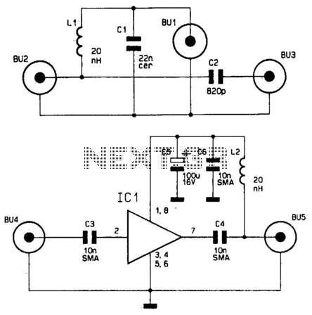
This wideband antenna preamplifier has a gain of approximately 20 dB from 40 to 860 MHz, covering the entire VHF, FM, commercial, and UHF bands. A phantom power supply delivers DC power to the preamplifier through the coaxial cable...
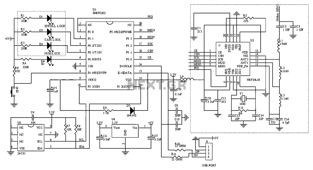
The circuit diagram for the receiving portion of a 2.4 GHz wireless keyboard is presented below. The 2.4 GHz wireless keyboard receiving circuit typically consists of several key components that work together to receive and process signals transmitted from the...
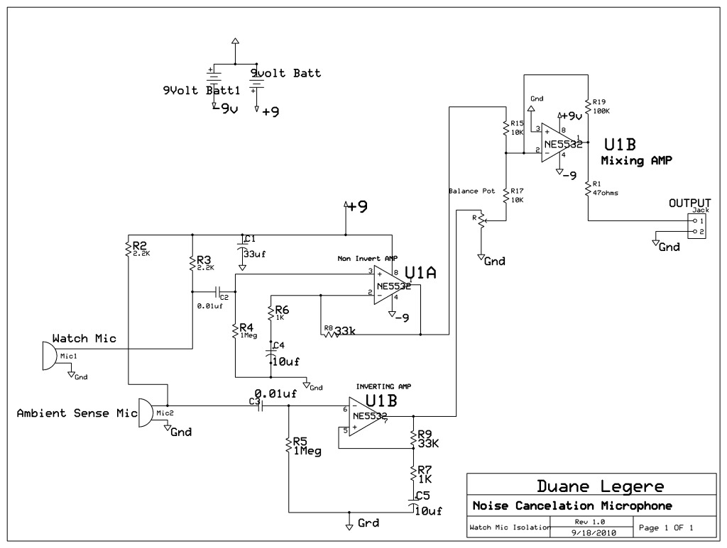
A microphone is designed to listen to a wristwatch while canceling ambient noise in the room. A circuit has been included, which is based on a headphone cancellation circuit. The schematic will be provided shortly. The suggested approach is...
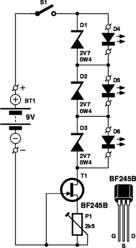
These small electronic lamps are quite practical and have a long lifespan. Approximately 40 years after Nick Holonyak invented the first LED, they have become nearly essential. Any dedicated electronics enthusiast typically keeps a few in their collection. Prior...