
2.4G wireless keyboard receiver part of the circuit

The 2.4 GHz wireless keyboard receiving circuit typically consists of several key components that work together to receive and process signals transmitted from the keyboard. The main components include an antenna, a radio frequency (RF) receiver module, a microcontroller, and associated passive components such as resistors and capacitors.
The antenna is responsible for capturing the RF signals transmitted by the wireless keyboard. It is designed to operate efficiently at 2.4 GHz, ensuring optimal reception of the signals. The RF receiver module demodulates the incoming signals, converting them from radio frequency to baseband signals that can be processed by the microcontroller.
The microcontroller serves as the central processing unit of the receiving circuit. It interprets the demodulated signals, translating them into commands that correspond to keystrokes made on the keyboard. The microcontroller may also include firmware that manages the communication protocol and handles any error correction necessary for reliable data transmission.
Additionally, passive components such as capacitors and resistors are used to filter noise and stabilize the power supply to the RF receiver and microcontroller. Proper design of the power supply circuit is crucial to ensure that the components operate within their specified voltage and current ranges, thereby enhancing the overall performance and reliability of the wireless keyboard system.
In summary, the 2.4 GHz wireless keyboard receiving circuit integrates an antenna, RF receiver, microcontroller, and passive components to effectively receive and process wireless signals, enabling seamless communication between the keyboard and the host device. This design is essential for achieving the desired user experience in wireless keyboard applications.2.4G wireless keyboard receiving portion circuit diagram as follows:
Related Circuits

This circuit was detailed in a recent edition of an amateur radio magazine. It enables operation in the 160 to 190 kHz band with a maximum power output of 1 W (license-free) in various modes such as CW, SSB,...
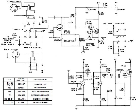
SHURE is an American corporation that manufactures consumer and professional audio electronics, including microphones, phonograph cartridges, and discussion systems. SHURE Incorporated is a well-established entity in the audio electronics industry, recognized for its innovative design and high-quality products. The company...
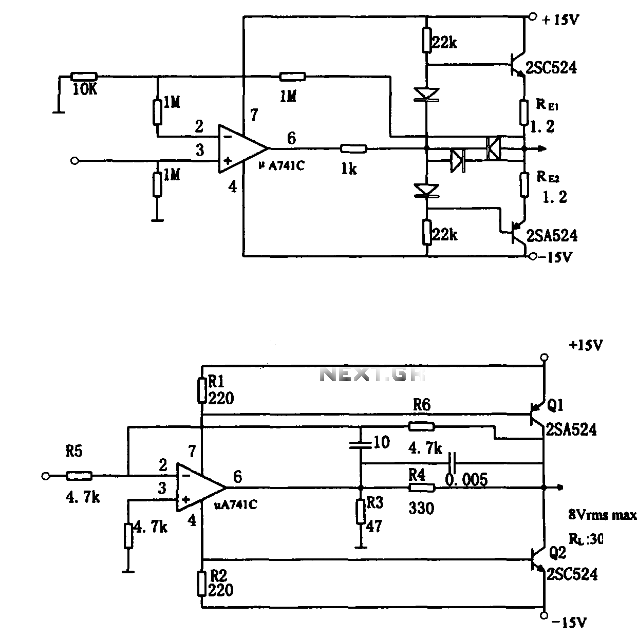
The direct coupling audio power amplifier utilizes an integrated operational amplifier. There are typically two practical configurations. The first configuration, depicted in (a), features a circuit structure that includes the output of the operational amplifier and a complementary symmetry...

This alarm circuit is designed to monitor a mains-powered smoke detector located in a shed used for dog kennels. It ensures complete isolation from the mains, allowing low-voltage (12V) cabling to connect to the alarm circuit situated inside the...

Although LEDs dominate the lighting market today, a standard flashlight bulb can still be a viable light-emitting option, particularly due to its simpler configuration compared to an LED. When the AC mains supply fails, transistor T1 becomes forward-biased, allowing...
This power supply was designed for use with the Simple hybrid amplifier published elsewhere in this issue. It is suitable for various applications as well. A cascade generator is utilized for the 170 V output, a switch-mode supply provides...