
AC Locomotive Auxiliary Equipment

The electrical system of electric locomotives is complex and requires careful integration of various components to ensure efficient operation and safety. Each auxiliary plays a crucial role in maintaining optimal performance levels while managing the thermal output generated during operation. The design considerations include not only the thermal management systems but also the reliability of the auxiliary motors, which are designed to operate in harsh environments. The use of AC three-phase squirrel cage induction motors offers advantages in terms of durability and low maintenance requirements, which are critical for the continuous operation of electric locomotives.
Furthermore, the transformer oil cooling system is essential for preventing overheating, which can lead to equipment failure and safety hazards. The integration of flow detection relays and protective relays enhances the safety mechanisms within the power circuit, ensuring that any malfunction in the cooling system triggers an immediate response to protect the locomotive's critical components. The relationship between the various auxiliary systems and the main power circuit underscores the importance of a well-coordinated design approach in electric locomotive engineering. Overall, the operational efficiency and safety of electric locomotives depend significantly on the effective functioning of these auxiliary systems, which are meticulously designed to meet the demands of modern rail transport.Electric locos derive tractive effort from Traction Motors which are usually placed in the bogie of the locomotive. Usually one motor is provided per axle but in some older generation of locos two axles were driven by a single Traction Motor also.
However apart from Traction Motors, many other motors and equipments are provided in electric locos. These motors are collectively known as the Auxiliaries. The aim of this article is to provide an insight into the various Auxiliary Machines provided in the Electric Locos operational on the Indian Railways. But to understand the reasons why these auxiliaries are needed, it is necessary to understand the manner in which the electric locos operate.
An important part of the electric loco is the Power Circuit. A short description of the power circuit of Electric Locos operational on the Indian Railways can be seen here. The article referred to describes the main components of the Power Circuit of the Electric Locomotive comprising of the following parts: A common feature running through all the above electrical equipments is that all of these generate a lot of heat during their normal operation.
Even when they are not in use, they might generate a nominal amount of heat. Normally any electrical equipment generates heat as by-product during operation. But traction vehicles tend to generate more heat than normal. This is because day-by-day the demand on traction vehicles is increasing. But an increase in the power output more or less translates into increased size of the relevent equipments too. But a major problem with traction vehicles is that you cannot increase their size beyond a certain limit.
This is due to "Loading Guage Restrictions". Hence, the power output of the locomotives has to be increased indirectly without increasing their size. This is done by "pumping"more power through the equipments and cooling them at a suitable rate at the same time.
Hence the different auxiliaries provided for cooling and other purposes in these locos is described below. All the motors are of the AC 3 Phase squirrel cage induction type and require very little maintenance and are simple and robust.
They are described with regard to their relationship to the major power equipments The transformer tank is filled with oil which serves two purposes. It provides enhanced insulation to the transformer and its surroundings and the oil absorbs the heat generated in the transformer and takes it away to the Transformer Oil Cooling Radiator.
The circulation of this oil is carried out by the MPH. A flow valve with an electrical contact is provided in the oil circulating pipe. As long as the oil is circulating properly, the contacts on the relay remain closed. However, in case the MPH fails or stops the relay contacts open which in turn trips master auxiliary protection relay Q-118. This trips the main circuit-breaker(DJ) of the loco. Thus the transformer is protected. The MPH circulates the transformer oil through a radiator array on top of the transformer. Air is blown over the radiator by the MVRH. This discharges the heat from the radiator into the atmosphere. A flow detecting relay is provided in the air-stream of the MVRH. The flow detector is a diaphragm type device. The flow of air presses the diaphragm which closes an electrical contact. This relay is known as the QVRH. In case the MVRH blower fails the the QVRH releases and trips the DJ through the relay Q-118. The transformer and its cooling equipment. The small vertical motor on top left is the MPH and the horizontal larger motor in the top centre is the MVRH and behind it is the oil cooling radiator.
Click for a larger view. One blower is provided for each of the rectifier blocks. As rectifiers are semiconductor devices, they are very sensitive to heat and hence must be cooled continously. The switching sequence of the MVSI blowers is setup in such a way that unless the blowers are runn 🔗 External reference
Related Circuits
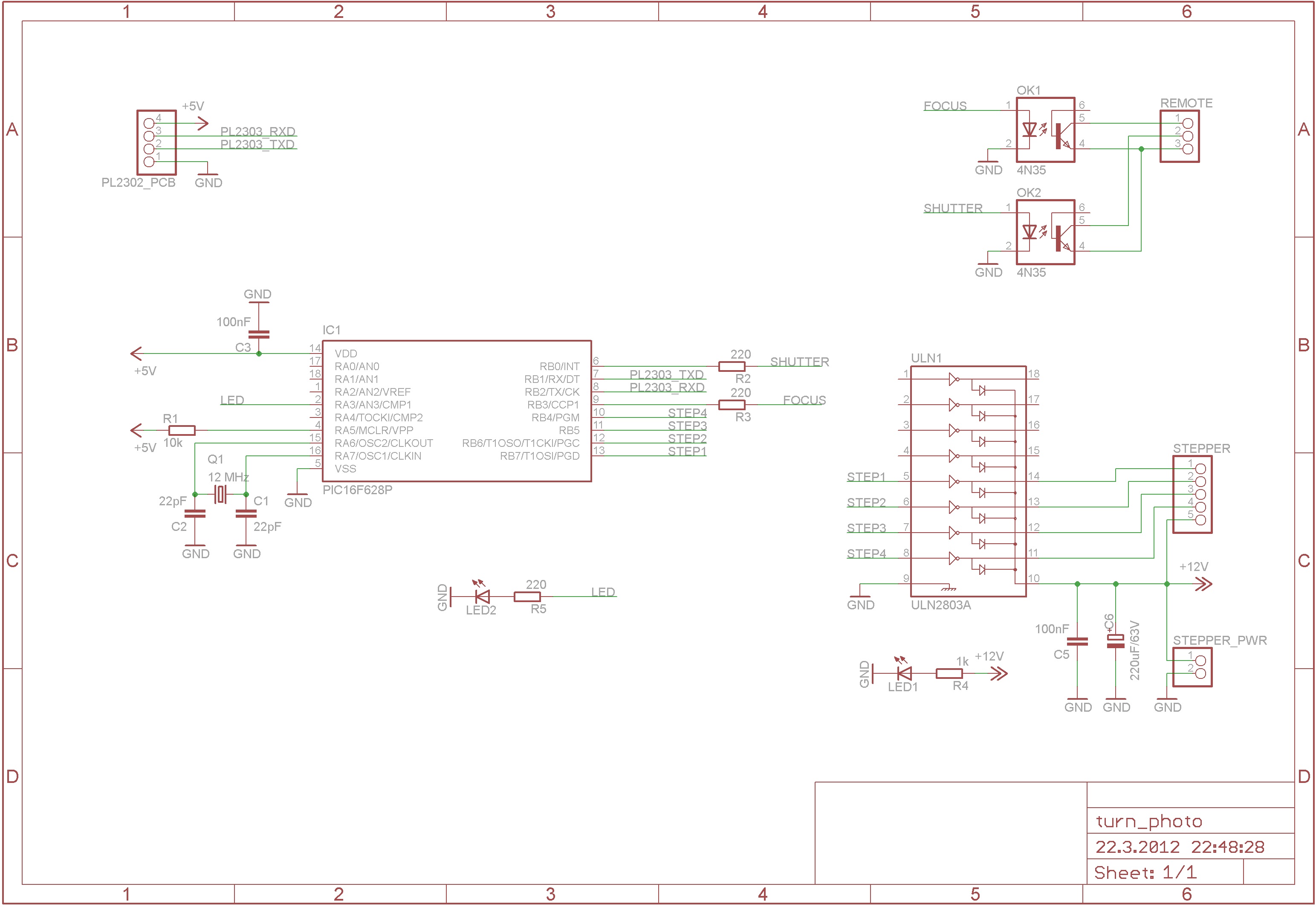
The device captures 360-degree photos, which are essentially animations made from multiple images of a product taken from different angles. It requires a controllable device that can take pictures at even intervals. As depicted in the accompanying image, a...
The 3GPPFDD_UE_RX is a test bench designed for testing the user equipment receiver in 3GPP FDD systems. It allows users to connect to an RF circuit device under test (DUT) and evaluate its performance through predefined measurements. This test...
The diagrams illustrate the startup sequence of the TEP-60 diesel engine starter in relation to current accumulators: 1 - battery current without a supercapacitor block (SCB) when the traction generator operates in starter mode; 2 - battery current with...
The DZ-2 was developed by RCA in Camden, NJ, for the U.S. Navy to function as a Radio Direction Finder in naval aircraft. With a contract date of June 30, 1939, the receiver exemplifies pre-war design. It operates using...
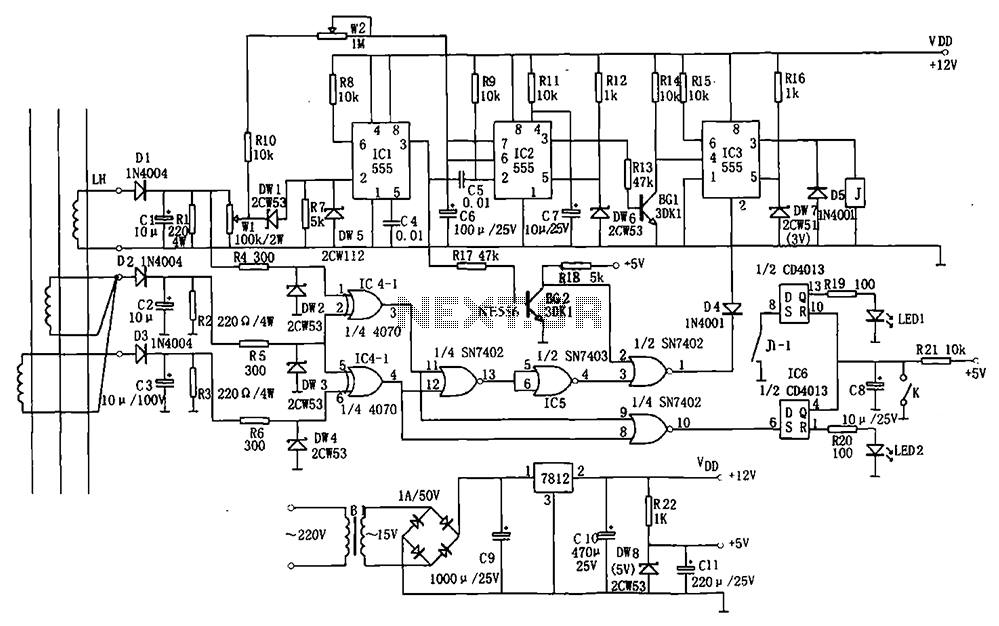
The electrical equipment overload and phase failure protection circuitry includes a +12V and +5V DC power supply, an AC transformer, voltage comparators, timers for blockade, a relay control circuit, and a phase loss protection circuit. The DC power supply...
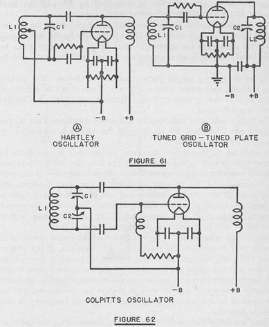
The tuned circuits of capacitance and inductance used in vacuum tube transmitter circuits are often referred to as "tank" circuits, as they serve as reservoirs of RF energy. Blocking capacitors are employed to create a high impedance path for...