
AC Motor Speed Controller Kit

The AC Motor Speed Controller Kit - K2636 is designed to regulate the speed of AC motors, making it suitable for various applications such as fans, pumps, and other motor-driven devices. The circuit employs a phase control technique, allowing for smooth speed adjustments by altering the effective voltage applied to the motor.
The core components of the circuit typically include a triac, which serves as the primary switching device, and a diac for controlling the triggering of the triac. The control circuit often integrates a potentiometer that enables the user to adjust the motor speed according to specific requirements.
In operation, the circuit receives an AC input voltage, which is then processed through the triac. The phase control method involves delaying the triggering of the triac during each AC cycle, effectively reducing the power delivered to the motor. This delay can be finely adjusted using the potentiometer, allowing for a wide range of speed control.
Additional components may include resistors and capacitors that help filter noise and stabilize the circuit, ensuring reliable performance. The design may also incorporate safety features such as fuses or thermal protection to prevent overheating and damage to the motor or the controller itself.
Overall, the K2636 circuit diagram represents a practical solution for controlling AC motor speed, providing flexibility and efficiency for various applications.The? following circuit shows about AC Motor Speed Controller Kit - K2636 Circuit Diagram. Features: normal dimmers the kit performs, with carbon . 🔗 External reference
Related Circuits
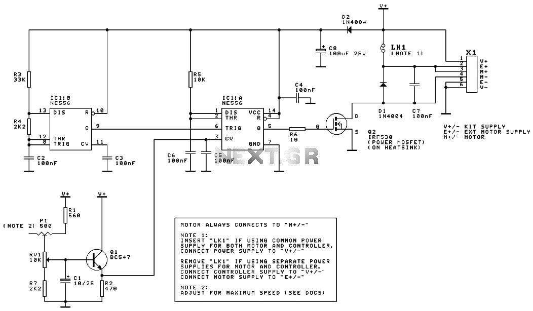
This is the schematic diagram of a DC motor speed controller circuit. The circuit utilizes two oscillators/timers that are configured as a Pulse Width Modulator (PWM). The timer chip used in this circuit is a dual NMOS timer/oscillator. The DC...
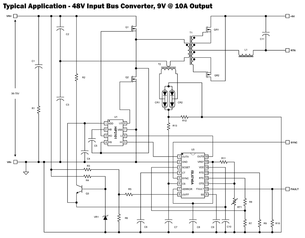
The ISL6740A is an enhanced PWM controller that incorporates built-in voltage feed forward functionality. It is pin and feature compatible with the ISL6740 double-ended pulse width modulation (PWM) voltage-mode controller, facilitating straightforward drop-in replacement in existing designs. Voltage feed...
Communication with the MCP3028 ADC chip is achieved through a straightforward serial interface that adheres to the SPI protocol. The PIC16F84 or PIC16F628 does not possess a hardware SPI peripheral. However, a software-implemented SPI protocol can facilitate communication with...
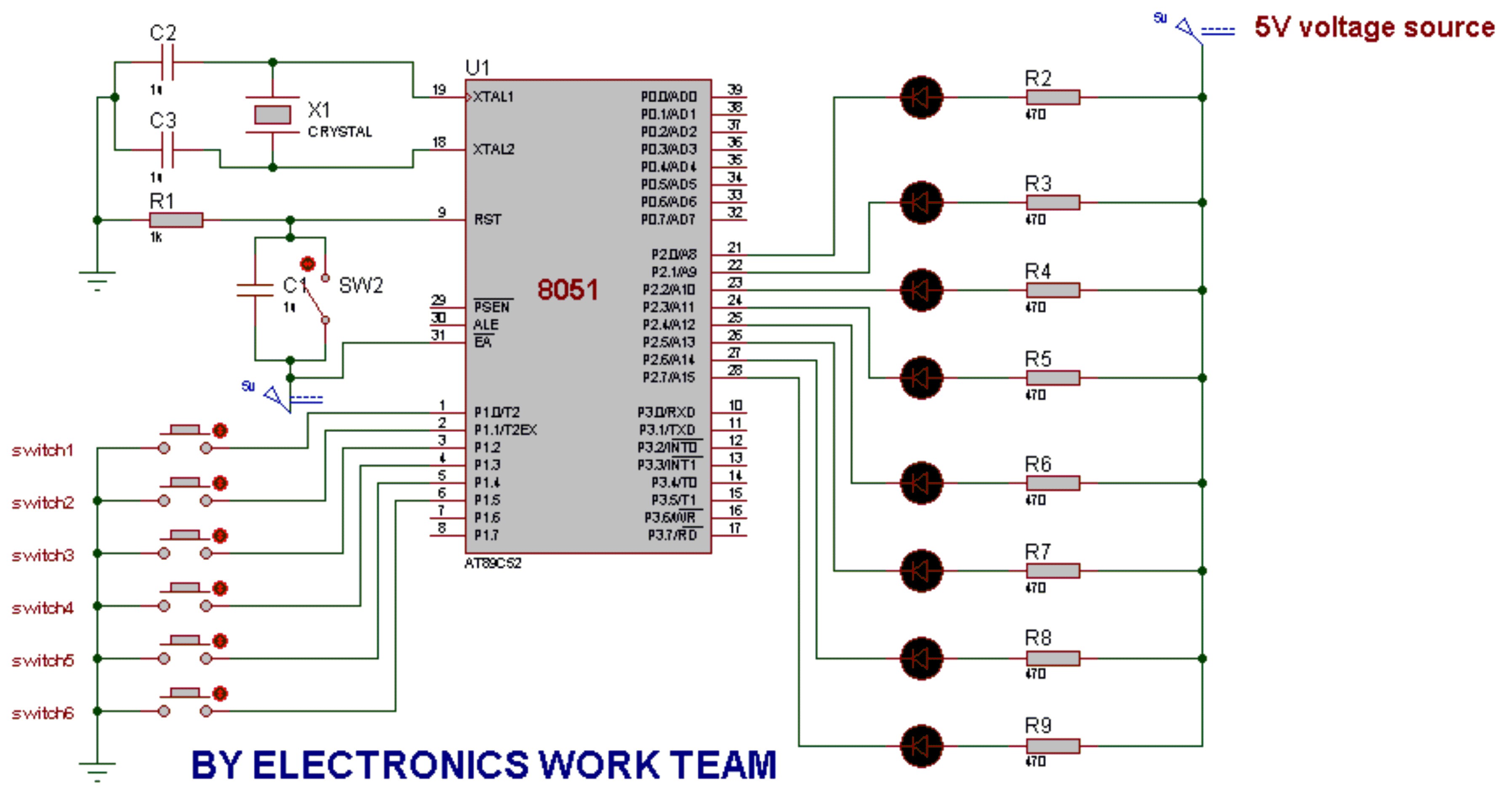
This post discusses the fundamental operation of the 8051 microcontroller using LEDs. The LEDs are connected to the P2 port, while six switches are connected to the P1 port of the 8051. By pressing various switches, the LEDs will...
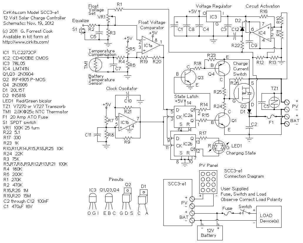
A 12 Volt solar power system can provide power to a wide variety of devices. Some examples include: lighting systems, cellular phones, CB and Ham radios, car stereos, televisions, recording equipment, fans, water pumps, and other low voltage DC...
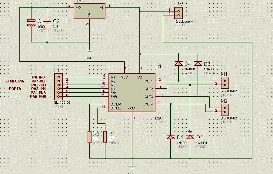
The circuit diagram includes M1 connected to Coil A of a stepper motor and M2 connected to Coil B of the stepper motor. Resistors R1 and R2 are 1 Ohm resistors used for current limiting. The circuit design involves a...