
DC Motor Speed Controller

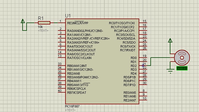
The DC motor speed controller circuit employs a dual timer configuration to generate PWM signals that control the speed of a DC motor. The two oscillators work in tandem, producing a variable duty cycle output that modulates the average voltage supplied to the motor, effectively controlling its speed.
The circuit typically consists of a 555 timer IC or a similar dual timer chip, which is configured in astable mode to generate the PWM signal. The output from the timer is fed into a transistor or MOSFET, which acts as a switch to control the power delivered to the motor. The duty cycle of the PWM signal can be adjusted by varying the resistances and capacitance in the timer circuit, allowing for fine control over the motor speed.
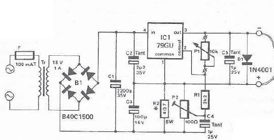
In addition to the timer and switching components, the circuit may also include additional elements such as diodes for flyback protection, capacitors for filtering, and resistors for setting the timing parameters. The inclusion of these components ensures stable operation and protects against voltage spikes that can occur when the motor is turned off.
Overall, this DC motor speed controller circuit is an efficient solution for applications requiring variable speed control, such as in robotics, conveyor systems, and various automated machinery. The use of PWM not only enhances the control over the motor speed but also improves energy efficiency compared to other control methods.This is the schematic diagram of DC motor speed controller circuit. The circuit applies two oscillators/timers which are connected as a Pulse Width Modulator (PWM). The timer chip which applied in this circuit will be an nmos dual timer/osc.. 🔗 External reference
Related Circuits
The shaft can be positioned at specific angular positions by sending a coded signal to the servo. As long as the coded signal is present on the input line, the servo will maintain the angular position of the shaft....
The advanced credit card, referred to as the "microcontroller super card," incorporates numerous innovative enhancements. The initial step involved verifying the code and subsequently uploading it to the Arduino board. The developed code enabled a counter to increment from...

The LTC3722-1 and LTC3722-2 phase-shift PWM controllers offer all necessary control and protection functions for implementing a high-efficiency, zero voltage switched (ZVS), full bridge power converter. The adaptive ZVS circuitry delays the turn-on signals for each MOSFET, independent of...
The page is about equipping an Atmel AVR microcontroller based system with a Prism WLAN interface. This document is intended for people that already have experiences with the AVR microcontrollers and teaches them how to add a cheap but...

The trembler (motion-activated) switch triggers an alarm for 5 seconds before automatically turning off. The circuit has a timeout period of 10 seconds to allow the trembler switch to stabilize. The trembler switch circuit operates by detecting motion through a...
An integrated voltage regulator connected in reverse to a mini drill allows for speed adjustment within specific limits, maintaining a constant speed regardless of load. The electronic speed control is achieved through a voltage regulator, which can power motors...