
AC Phase control

The AC phase control circuit is designed to provide efficient regulation of power in AC loads, utilizing a triac as the main switching component. The zero-crossing detector employs an opto-isolator to ensure that the low-voltage control circuit remains electrically isolated from the high-voltage AC line, enhancing safety during operation. When the AC voltage crosses zero, the detector outputs a clean 5V pulse, which is fed into the Arduino. The Arduino is programmed to respond to this pulse using interrupt-driven programming, allowing for precise timing of the triac gate pulse.
The triac is controlled through its gate terminal, which requires a brief voltage pulse (t2) to initiate conduction. The duration of this pulse is critical; it must be long enough to ensure reliable triggering of the triac but short enough to maintain control over the power delivered to the load. The timing sequence is managed by the Arduino's internal timer, which counts clock cycles to determine the appropriate moment to activate the triac after a zero crossing.
As the AC signal oscillates, the triac's conduction can be delayed by varying the duration of the off-time (t1), effectively controlling the average power delivered to the load. This method of phase control allows for smooth dimming of lights or modulation of heating elements without the noise and flicker associated with other control methods. The system's responsiveness is enhanced by the use of interrupts, ensuring that any changes in the AC waveform are quickly addressed, maintaining synchronization between the control circuit and the AC line.
Overall, this AC phase control circuit represents a practical application of microcontroller technology in power management, providing a reliable, efficient means of controlling AC loads while ensuring safety through isolation and precise timing.One method of controlling power to ac circuits uses a triac to turn the power on and off at precisely timed intervals that are synchronized with the ac signal. This method is called AC phase control. It is the method used in many light dimmer and heater power control circuits. Using an Arduino microcontroller with some simple circuitry, we can monitor the ac wave to determine the
proper time to turn the power on and off with the triac. The circuit I used to do this is shown below. The circuit consists of an opto-isolated zero-crossing detector and a opto-isolated trigger circuit for the triac. The opto-isolators are necessary to keep the low voltage signal circuits away from the power circuits and provide an appropriate level of safety.
As will all circuits involving mains voltage, make sure you know what you are doing. The zero-crossing detection circuit provides a 5v pulse every time the ac signal crosses zero volts. We detect this with the Arduino and leverage interrupts to time the trigger circuit precisely in synchronization with these zero-crossing events. The method for power control is shown in the diagram below. Once a zero crossing is detected, the triac remains off for a controlled amount of time (t1). The longer this time is, the less power the ac circuit receives. Once the off-time , t1 has elapsed, the microcontroller turns on the triac by applying a voltage to the gate (shown in red).
Once turned on, the triac will remain on even after the gate voltage has been removed. It will turn off if the gate voltage is zero the next time the ac wave crosses zero. Because of this, we do not need to take care to turn the triac off when the ac signal crosses zero again. All we need to do is to ensure that the triac gets turnd off inside of the period of ½ wave (t3). The duration of the gate pulse (t2) is determined by a minimum requirement of the traic. If this pulse is too short, the traic will not fire Once the second zero crossing occurs, sice there is no voltage on the gate, the triac remains off until triggered again in the next ½ cycle.
The net result here is that we chop parts of the wave out resulting in lower average power. This is essentially how one accomplishes PWM control of an AC wave. We will be using interrupts and the arduino timer to precisely control the timing of the triac gate. To get a feel for the time intervals, we need to look at the AC signal and the Arduino clock. The AC signal (in the US anyway) is 60 Hz. What this means is that the AC signal crosses zero, reaches peak positive voltage, crosses zero, reaches peak negative voltage and returns to zero 60 times each second. The period (length of time this takes) is 1/60 or 0. 01667 seconds (16. 67 milliseconds). A half cycle (the time between two zero-crossings) occurs in 8. 33 milliseconds. This is t3 in the figure above. The Arduino clock runs at 16 MHz, which is 16, 000, 000 cycles per second: one clock cycle takes 0. 0625 microseconds. A single half cycle of the 60 Hz AC signal contains 133, 333 clock cycles. This is important because we will be determining the time intervals by clock counts in the Arduino code, not by seconds.
There is quite a bit of good information on use of interrupts with the Arduino out on the web so I won`t cover that in much detail here. Basically the way an interrupt works is that when some event happens (either internal or external to the microprocessor), the microprocessor immediately stops what it is doing to service the interrupt.
This allows the microprocessor to handle very time sensitive events such as the AC Phase control task here. // AC Control V1. 1 // // This arduino sketch is for use with the heater // control circuit board which includes a zero // crossing detect fucntion and an opto-isolated triac.
// // AC Phase control is accomplished using the internal // hardware timer1 in the arduino // // Timing Sequence // * timer is set up but d 🔗 External reference
Related Circuits
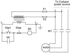
The most challenging aspect of interpreting ladder diagrams, particularly for individuals familiar with electronic schematic diagrams, is the representation of electromechanical relays. The operation of a motor control circuit should be explained, detailing what occurs when the "Run" switch...
This circuit allows for amplifier volume control without the need for a potentiometer, utilizing an IC DS1669. The operating voltage for this type of IC ranges from 4.5 volts to 8 volts; however, in this circuit, it is used...
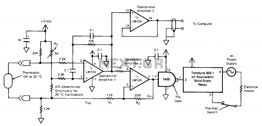
The circuit switches the current to an electrical heater on and off to maintain the temperature of a room at 25 ±0.5°C. The temperature sensor is a thermistor that provides a differential input (for reduced noise) to an operational...
The AquaCont is an electronic system which permits to manage and to monitor most of the parameters of all the electric devices that can be found in an aquarium. The PIC18F4520 used to realize it combines a real-time clock...
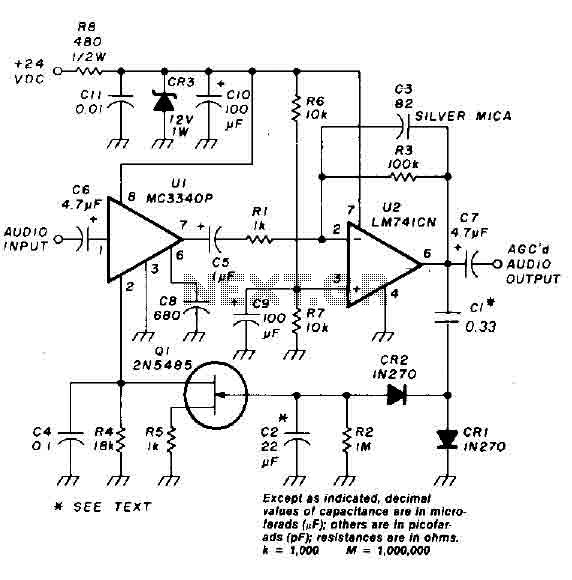
An audio signal applied to the input VI is passed through the operational amplifier 741, designated as U2. After amplification, the output signal V2 is sampled and sent to a negative voltage doubler/rectifier circuit composed of diodes CR1 and...
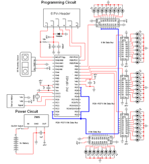
The personal radar system utilizes the PIC microcontroller PIC18F452 as a hobby project. The attached circuit diagram of the radar may appear simple; however, careful analysis of the PIC18F452 radar circuit is necessary to prevent damage. This personal radar...