
contruction of personal Radar System using PIC MIcrocontroller PIC18f452

The personal radar system based on the PIC18F452 microcontroller is a compact and efficient design intended for hobbyists and educational purposes. The circuit typically consists of the microcontroller, IR sensors, and necessary supporting components such as resistors, capacitors, and power supply circuitry. The PIC18F452 serves as the central processing unit, executing the programmed instructions to control the radar's operation.
The IR sensors function as the primary detection mechanism, emitting infrared light and measuring the reflected signals to determine the distance to an object. Depending on the specific sensor used, the radar can operate effectively within different ranges. For example, short-range sensors may be employed for detecting objects within 4-30 cm, while medium-range sensors can extend the detection capability to 20-150 cm, and long-range sensors can reach up to 1-5.5 m.
The design incorporates a simple user interface, which may consist of LEDs or an LCD display to provide real-time feedback on the detected distance. The output can be configured to trigger alarms or notifications based on proximity thresholds, enhancing the system's functionality for various applications such as obstacle detection, security systems, or even robotic navigation.
The circuit design requires careful attention to component selection and placement to ensure reliable operation. Proper power management is crucial, as the PIC microcontroller and sensors may have specific voltage and current requirements. Additionally, the microcontroller's programming must be meticulously crafted to handle sensor data processing, decision making, and output control to achieve the desired functionality of the personal radar system.Personal Radar System using PIC MIcrocontroller PIC18f452 is a microcontroller hobby project. The circuit diagram of radar is attached here below seemed a little bit simple schematic but you need careful reading of PIC18f452 radar circuit to avoid any damage. The project of personal Radar System using PIC MIcrocontroller PIC18f452 uses three main devices to create the personal radar system which are listed as below: The main function of the project is to create and have a simple functionality of a working IR radar system. The system will only be required to measure close proximity at an angle of 90 degrees as seen in the example above.
The range of system is roughly 4-30cm, 20-150cm & 1m-5. 5m depending upon which sensor you choose to use. 🔗 External reference
Related Circuits
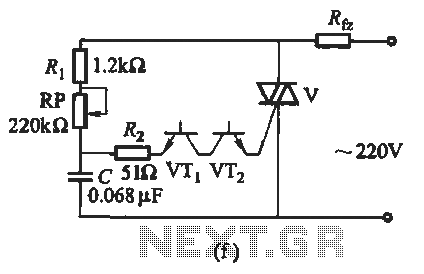
The introduction for a unidirectional thyristor trigger circuit is also applicable to the TRIAC. Various configurations are presented in Figure 16-28. Figures 16-28 (a) and (b) illustrate a direct trigger circuit; Figure 16-28 (c) depicts a dual diode trigger...

This circuit operates as an astable multivibrator. With switch S9, an octave can be chosen. The tones are set by P1 to P8. Pressing S1 to S8 displays the corresponding note; pressing two buttons at the same time gives...
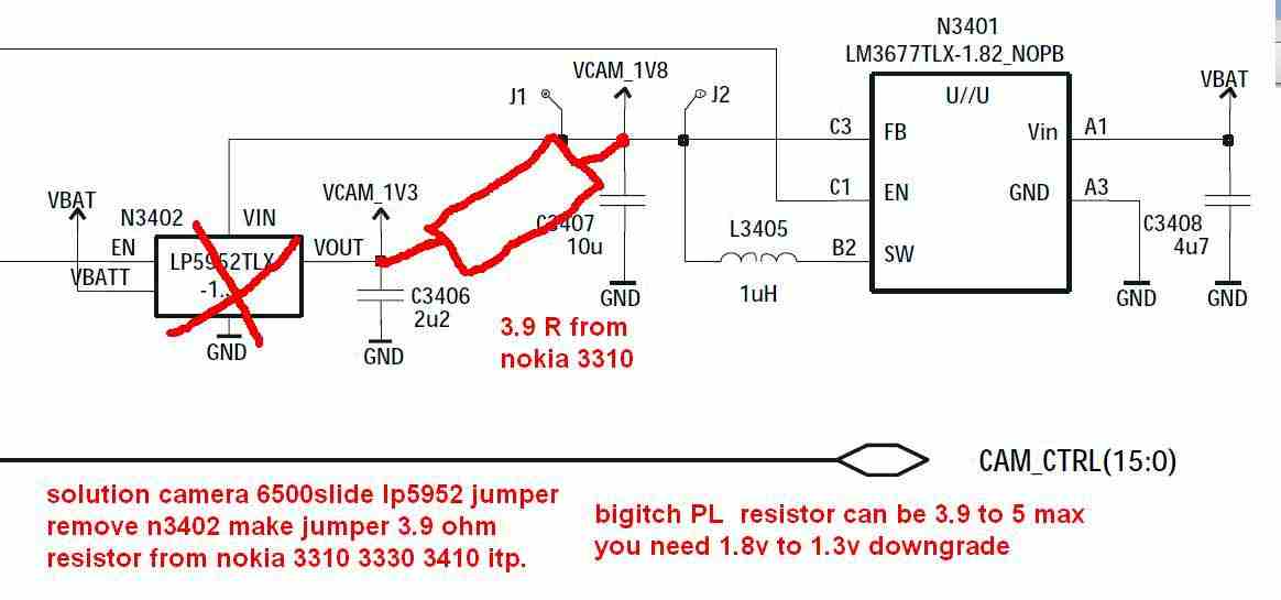
The Nokia 6500 camera issue, characterized by messages such as "camera operation failed" or a blank camera display, can potentially be resolved through a simple workaround. The accompanying images illustrate the Nokia 6500 slide camera problem and suggest creating...
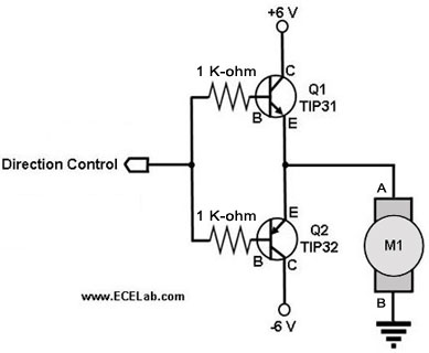
The following circuit illustrates a two-transistor DC motor driver circuit diagram. This circuit utilizes the TIP32 transistor. Features: operates in... The two-transistor DC motor driver circuit is designed to control the operation of a DC motor using two NPN transistors,...
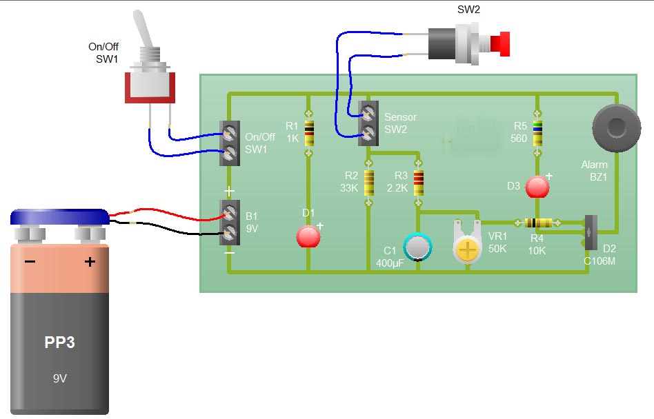
When the sensor switch SW2 is pressed, the LED D3 and the alarm are activated for a certain duration. The timing of the circuit is determined by the resistor R3 and capacitor C1. Additional details regarding the RC circuit...
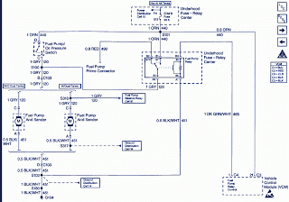
Pump prime connector, power distribution cell, fuel pump and sender, dual tanks, fuel pump balance relay, vehicle control module, underhood fuse relay, ECM fuse. The described components are integral to the operation and management of a fuel system in a...