
Active AM Radio Antenna Amplifier / Preamplifier Circuit

The antenna amplifier circuit is designed to enhance the reception capabilities of AM radio receivers by amplifying weak signals from a telescopic whip antenna. The use of two NPN transistors and a MOSFET allows for efficient signal processing, while the varicap diodes enable fine-tuning of the frequency response. The 330µH inductor/coil serves as a critical component for tuning across the medium waveband, providing flexibility for different frequency ranges.
The gain control feature, facilitated by RV1, allows users to adjust the amplification level based on signal strength. This is particularly useful in environments with varying signal conditions, enabling optimal reception without distortion from strong signals. The output impedance of 50 ohms ensures compatibility with standard radio receivers, facilitating straightforward integration into existing systems.
The dual-gate MOSFET configuration not only enhances selectivity but also improves overall performance through its ability to handle varying input signals effectively. The zener diode provides stability to the power supply, ensuring consistent performance of the amplifier circuit. The composite amplifier configuration, utilizing Q2 and Q3, further enhances the circuit's ability to drive low impedance loads, making it suitable for a wide range of applications.
For users interested in multi-band operation, the circuit's design allows for easy modification of the inductor values. By incorporating switches or relays, users can quickly adapt the circuit to operate efficiently across different frequency bands, making this antenna amplifier a versatile solution for AM radio applications.The antenna amplifier circuit has a part count of about 40, using the following active parts: 2 NPN transistors (BC548`s), 1 MOSFET (BF981), 2 Varicap diodes (KV1235), as well as a 6v2 zener-diode. there is and a 330uH (micro Henry) inductor / coil, which can be modified for operation on other frequency bands.
Designed to work with a telescopic wh ip antenna, the amplifier circuit operates in the typical AM / MediumWave band of 550 - 1650 kHz (kilohertz), with a power requirement of 12 Volts DC. The circuit also has a gain control feature, so weather signals can be amplifier more, if need be. This amplification alteration is provided via, RV1 The amplifier circuit`s output impedance is 50 Ohms, which is the standard for all of radio receivers, so it ought to work well along with your AM receiver.
This circuit is designed to amplify the input from a telescopic whip antenna. The preamplifier is designed to cover the medium waveband from about 550Khz to 1650Khz. The tuning voltage is supplied via RV2, a 10k potentiometer connected to the 12 Volt power supply. RV1 is the gain control allowing weak signals to be amplified or strong signals to be attenuated. The control voltage is applied to gate 2 of TR1, a dual-gate MOSFET, the signal voltage applied via gate 1; the input signal being double tuned via the 330uH coil and the two KV1235 varicap diodes at the MOSFET`s input and by the same components at the BF981 MOSFET`s drain terminal. Both tuned circuits provide high selectivity across the entire tuning range. To aid stability the MOSFET stage is fed from a 6. 2V zener stabilized supply. To drive low impedance (50 ohm) receivers, the medium output impedance of the BF981 stage is enhanced by the composite amplifier made from Q2 and Q3.
Q2 is operating in common emitter boosting voltage levels by just over 2, Q3 is operating in emitter follower providing the circuit with low output impedance. Finally this active antenna can be used on other bands by changing the values of the 330uH coils. To perform on multiple bands switches or relays can be used to change the value of the coils. 🔗 External reference
Related Circuits
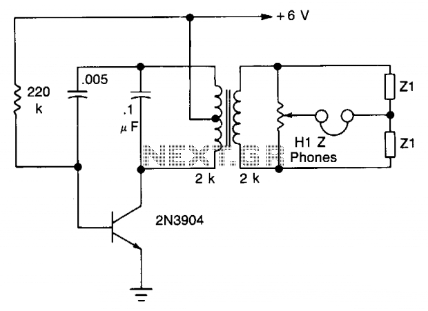
The transistor is configured as an audio oscillator, utilizing an audio transformer in the collector. The secondary winding is connected to a linear potentiometer. The ratio between the two sections of the potentiometer from the slider is proportional to...
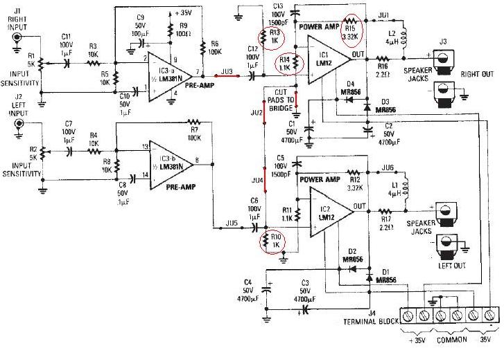
The LM12 audio amplifier circuit is designed to deliver high output power for 8 ohm or 4 ohm load impedances. The maximum output power provided by the LM12 audio amplifier is approximately 60 watts for a 4 ohm load...
Although the inputs are differential, the right amplifier has a bias current greater than 800 nA. Therefore, the input coupling capacitor should be considered. It is important to note that the resistance value on the input side should also...
A simple 3-way crossover, intended for triamping Hi-Fi systems. This is a conventional 12dB / Octave unit, and cannot be expected to have the same performance as a Linkwitz-Riley aligned filter network. It will still be a vast improvement...
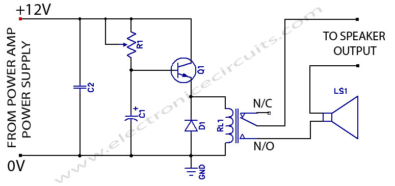
When powering on a power amplifier, a loud thump sound occurs due to a sudden heavy discharge current through the speaker. This current has the potential to damage the speaker, particularly in the case of a direct-coupled amplifier. The phenomenon...
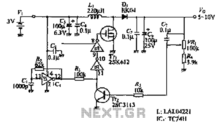
The design of the power supply circuit diagram utilizes an oscillator circuit from the 74HC series of CMOS logic circuits, with a MOSFET as the switching device. This configuration allows for the development of small-scale power supplies suitable for...