
active filters
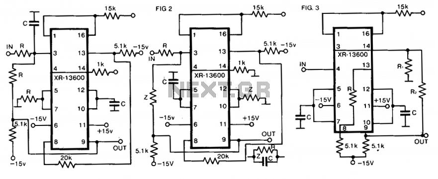
The all-pass filter is a unique topology in the realm of signal processing. Its primary function is to alter the phase of the input signal without affecting its amplitude, making it particularly useful in various applications such as phase correction in audio systems and in digital signal processing where phase relationships are critical. The all-pass filter can be implemented using operational amplifiers (op-amps) in various configurations, such as first-order or higher-order designs, depending on the required phase shift.
The design of an all-pass filter typically involves selecting appropriate resistors and capacitors to achieve the desired phase response across a specified frequency range. The frequency response can be tailored by adjusting component values, allowing for flexibility in design. The phase shift introduced by the filter can be calculated using the formula derived from the transfer function of the circuit, ensuring that the filter meets the specific requirements of the application.
In practical implementations, attention must be given to the choice of components, particularly the capacitors, as their characteristics can significantly influence the performance of the filter. Using high-quality capacitors, such as polyester or polypropylene, ensures minimal distortion and stable operation across varying temperatures and voltages. Additionally, the design should incorporate provisions for low-impedance sources to prevent oscillations and ensure signal integrity.
Overall, while the all-pass filter may appear straightforward, its applications and implications in signal processing are profound, providing essential phase manipulation capabilities without compromising signal strength. This characteristic makes it an invaluable tool in the toolkit of engineers working in audio, telecommunications, and various other fields that rely on precise signal control.There is one class of filter called "all-pass" that does not affect the response, only phase. While at first look this might be thought rather pointless, like all circuits that have been developed over the years it often comes in very handy. Filters also affect the transient response of the signal passing through, and extreme filters (high order types or filters with a high Q)
can even cause ringing (a damped oscillation) at the filter`s cutoff frequency. In some cases, this doesn`t represent a problem if the ringing is outside the audio band, but can be an issue for filters used in crossover networks (for example). If you are not already familiar with the concept of filters, it might be better to read the article Designing With Opamps - Part 2, as this gives a bit more background information but a lot less detail than shown here.
There is some duplication - the original article was written some time ago, and it was considered worthwhile to include some of the basic info in both articles. Filters are used at the frequencies where they are needed, so the filters described here need to be recalculated.
I have normalised the frequency setting components to 10k for resistors, and 10nF for capacitors. This provides a -3dB frequency of 1. 59kHz in most cases. Increasing capacitance or resistance reduces the cutoff frequency and vice versa. Capacitors used in filter circuits should be polyester, Mylar, polypropylene, polystyrene or similar. NP0 (aka C0G) ceramics can be used for low values. Choose the capacitor dielectric depending on the expected use for the filter. Never use multilayer ceramic caps for filters, because they will introduce distortion and are usually highly voltage and temperature dependent.
Likewise, if at all possible avoid electrolytic capacitors - including bipolar and especially tantalum types. Note Carefully: Nearly all filter circuits shown expect to be fed from a low impedance source, which in some cases must be earth (ground) referenced.
Opamp power connections are not shown, nor are supply bypass capacitors or pin numbers. All circuits are functional as shown. Also not shown are output `stopper` resistors from opamp outputs. These must be included for any signal that leaves an opamp and connects to the outside world using a shielded cable. Most opamps will oscillate if a resistor is not used in series with the output pin. 100 ohms is a convenient value, but it can be lower (less safety margin) or higher (higher output impedance).
The following is actually a fairly small sample of all the different topologies, but the examples have been selected based on their potential usefulness. Some of the circuits shown are extremely common, others less so. In the general discussions about filter properties I have avoided heavy mathematical analysis. The maths formulas provided are enough to allow you to configure the filter - few readers will want to perform detailed calculations and they are not generally useful other than for university exams.
The common terminology of filters describes the pass-band and stop-band, and may refer to the transition-band, where the filter passes through the design frequency. Q is a measure of `quality`, but not in the normal sense. A high-Q filter is not inherently `better` than a low-Q design, and may be much worse for many applications.
In some cases, the term `damping` is used instead, which is simply the inverse of Q (i. e. 1/Q). It is generally defined that the -3dB frequency is the point where the output level has fallen by 3dB from the maximum level within the passband. This means that if a filter produces a 1dB peak before rolloff, the -3dB point is then actually 2dB below the average level.
I tend to disagree that this is the most 🔗 External reference
Related Circuits
Using a modified equal-element design for a lumped-circuit lowpass filter has several advantages over the well-known equal-element design. The modified design exhibits superior passband performance with only modest degradation of stopband selectivity. Moreover, the modified design is simple and...
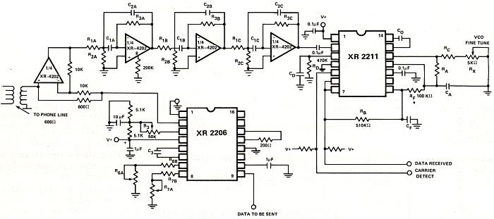
Nowadays every institution needs automation. As a part of college automation, a project has been developed for a Voice Interactive System for College Automation. This project allows users to quickly access student attendance and marks through the telephone line...
The circuit presented operates as a bandpass filter, with the transfer function derived from FBP(s) = 1 + s/Qo + s²/w₀². The cut-off frequency, denoted as ω₀, and the quality factor (Q-factor) are defined by ω₀ = g/C and...
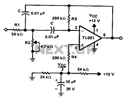
The circuit is a two-pole active filter utilizing a TL081 operational amplifier. This type of circuit is applicable only for quality factors (Qs) less than 10. The component values for this filter are determined using specific equations. The two-pole active...
The calculator computes the gain and output impedance of a common plate load mixer. Each input channel controls a separate grid, which affects the plate current through the common plate load resistor RL and the cathode resistor RK. The...
This application note aims to introduce filter designers to the basics of active filter design using monolithic integrated circuit operational amplifiers (op-amps). It includes a table of transfer functions and network equations for high-pass, low-pass, band-pass, and band-reject filters....