
Universal active filter

The described circuit functions as a versatile filter capable of bandpass, high-pass, and low-pass operations, depending on the configuration of its components. The transfer function highlights the relationship between the input and output signals, revealing how the circuit selectively allows certain frequency ranges to pass while attenuating others.
The cut-off frequency (ω₀) is a critical parameter, determining the point at which the filter begins to attenuate frequencies. It is influenced by the values of the capacitor (C) and the transconductance (g). In practical applications, the transconductance is a measure of how effectively the circuit can convert input voltage changes into output current changes, and it is temperature-dependent.
The Q-factor, a dimensionless parameter, characterizes the selectivity and bandwidth of the filter. A higher Q indicates a narrower bandwidth and more selective filtering, while a lower Q results in a broader bandwidth. The relationship between the Q-factor and the resistor values (R₁ and R₂) allows for fine-tuning of the filter characteristics in real-time applications.
The transition from a bandpass to a high-pass filter by interchanging the capacitor and resistor is a common practice in filter design, allowing for flexibility in circuit applications. The low-pass filter configuration, as indicated in the schematic, emphasizes the role of parallel connections in achieving desired frequency response characteristics.
Overall, the circuit's design can be adapted for various applications, including audio processing, communication systems, and signal conditioning, where control over frequency response is essential. The ability to independently adjust gain and Q-factor provides enhanced control over the circuit's performance, making it suitable for a wide range of electronic applications.The circuit as shown gives the bandpass operation the transfer function calculated from FBP(s) = where = 1 + s/Qo>0 + s2/w02. The cut-off frequency, 0, and the Q-factor are given by 0 = g/C and Q = gR/2 where g is the transconductance at room temperature.
Interchanging the capacitor C with the resistor R at the input of the circuit high-pass operation is obtained. A low-pass filter is obtained by applying two parallel connections ctf R and C as shown in Fig. 2. The low-pass operation may be much improved with the circuit as given in Fig. 3. Here the gain and Q may be set up separately with respect to the cut-off frequency according to the equations Q = 1/fB = 1 + R2/R!, A = Q2 and 0 = g ffi/C.
Related Circuits
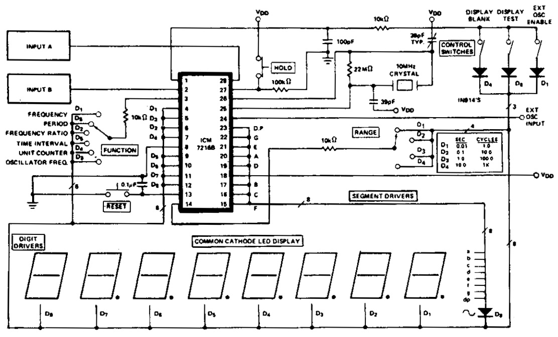
The ICM7216A can be utilized as a minimal component complete Universal Counter. This circuit is capable of handling input frequencies of up to 10 MHz at INPUT A and 2 MHz at INPUT B. In cases where the signal...
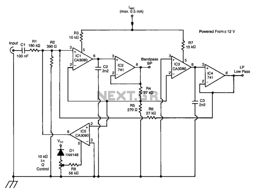
A standard dual integrator filter can be constructed using a few CA3080 operational amplifiers. By varying the parameters L, A, B, and C, the resonant frequency can be swept over a range of 1000:1. At IC1, three current-controlled integrators...
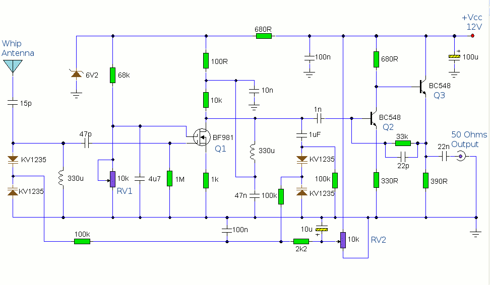
The antenna amplifier circuit comprises approximately 40 components, featuring two NPN transistors (BC548), one MOSFET (BF981), two varicap diodes (KV1235), and a 6.2V zener diode. It includes a 330µH inductor/coil, which can be modified for operation on different frequency...
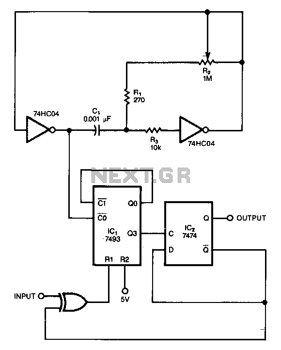
This circuit filters noise, such as glitches and contact bounce, from digital signals. It can be easily adjusted for a wide range of noise frequencies. The circuit's output changes state only if the input differs from the output long...
In older amps is usually a phono input. Today, this used less and less, and it would be useful if the input and line input can be used. This circuit goes. The circuit is actually an attenuator and a...
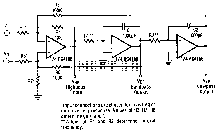
A generalized circuit diagram of the two-pole state-variable active filter is presented. This state-variable filter can be configured as either inverting or non-inverting and is capable of providing three simultaneous outputs: low-pass, bandpass, and high-pass. By incorporating an additional...