
Active Loudspeaker Amplifier with SKT4042


The active loudspeaker circuit described incorporates a 2-way crossover design, effectively managing the frequency distribution between the woofer and tweeter. The crossover frequency is set at 3100 Hz, allowing for a seamless transition between the two drivers. The use of operational amplifiers, such as the TL071 and TL072, facilitates precise signal processing, ensuring minimal distortion and high fidelity sound reproduction.
The input stage, represented by IC1, serves to adapt the incoming audio signal, preparing it for filtering. The high-pass filter implemented around IC2 allows frequencies above 3100 Hz to pass through, while the low-pass filter associated with IC3 allows frequencies below this threshold. The inclusion of a trimmer potentiometer (TR1) enables fine-tuning of the balance between the woofer and tweeter, typically requiring a reduction in the tweeter level by approximately 10% to achieve a harmonious sound output.
The power amplification stage employs hybrid ICs (IC4 and IC5), which provide robust output suitable for driving the respective speakers. These amplifiers are capable of delivering 80W at 8 ohms, and alternative IC models can be substituted as long as the power supply voltage is adjusted accordingly. The design incorporates protective features, including a relay (RL1) that disconnects the speakers during power interruptions or DC offset conditions, thereby safeguarding the drivers from potential damage.
The overall construction of the circuit is housed within an aluminum chassis, ensuring effective heat dissipation and structural integrity. The toroidal transformer provides a clean power supply, minimizing interference. The performance of the loudspeaker is contingent upon the quality of the components used, particularly the tweeter and woofer, as well as the enclosure design, which plays a crucial role in sound reproduction quality.Active loudspeakers have a lot of advantages concerning simple loudspeakers that use passive components for the elements concretisation of segregation of frequencies. In the case of active loudspeakers we have, proportionally, bigger build cost, because each loudspeaker is led by his own power amplifier.
In properly drawn active loudspeaker, the quality of sound is much better and the distortions very low, because it does not use inductors and large capacitors in the road of signal. All capacitors exist in the signal road, they have very small value and they are very good quality. This does not mean that one well drawn passive loudspeaker is not good, perhaps better than one active.
On the contrary one active loudspeaker is enough difficult in the manufacture. In the [Fig.1], exist a circuit of 2-way active loudspeaker. As we see also in the Block diagram [Fig.2], exist one classic 2-way crossover with cross frequency fc=3100HZ [-24dB/oct]. This frequency was selected, because it is near in the cross frequency of many speakers of trade, it can however change and be adapted in your own speakers choice, it?s enough you use the types that give for calculation [Fig.3].
The IC1 makes the input adaptation, the filters round the IC2 creates a high-pass filter of frequencies, for frequencies above Fc=3100HZ, on the contrary the components round the IC3 creates a low-pass filter, for frequencies under 3100HZ. With the trimmer TR1 in the line of high frequencies we can adaptable, if it needs, the level between the two speakers.
Usually it will need we lower at 10% the level tweeter concerning woofer. In a lot of points of filter exist capacitors and resistors that are not used, but are there for future changes, in a other cross frequency, as the R6 and R10 that are not used. To the next stage the two outputs of filter are drive to the two power amplifiers, the IC4 for the high frequencies and the IC5 for low.
Those of are two hybrid IC by Sanyo, with output power 80W/8ohms, with very good characteristics and sound. It can become change with other type of series as STK4036, STK4038, STK4040, with proportional modification of power supply voltage.
The particular line is used in enough active loudspeakers, with very good results. Good it?s used type STK4042XI, because it has more modern internal designing, concerning type STK404II. Filters RLF1-2 in the exit of amplifiers are constituted by resistor R27 or R38 and a inductor wounded round this, in three layers.
The inductor is made with 25 until 30 coils of cupreous wire, diameter 1mm. In the amplifiers output exist the contacts of relay RL1, who is checked by the protection from DC and delay system. This circuit is found round the IC6 and works as follows: When the circuit is supplied exist a delay 5 sec in the connection speakers above in the amplifiers outputs, so that are not pass the charge capacitors noises.
On the contrary when we break the power supply, then RL1 disconnect very fast the speakers from amplifiers, so that is not heard the discharge noise of capacitors. At the same time the circuit protects the speakers from DC voltages, that will be presented for any reason, in the output Of power amplifiers, opening the contacts of RL1 and disconnect, very fast the speakers.
The circuit operation of protection/ delay becomes obvious from Led [D20], which should be placed in obvious point in the speakers box. The connections it appears in the Fig. 2. The transformer is toroidal, good quality. The main pcb, the heatsink, the transformer, the rectifier bridge BR1, as also all the components that appear except main pcb, are placed in a aluminium piece of suitable dimensions which is adapted in dimensions of the speakers box and is placed in the back side of box.
Two power amplifiers IC4 and IC5 clinched above in the heatsink. The total performance of loudspeaker depends always from the characteristics of units Tweeter and Woofer, that will be used in this, also from the designing and the quality of the box. Older i used in the place tweeter the T33? and woofer the B200G by KEF. Part List R1-21-32-25-36-58=1 Kohms C19-20-52=10uF 25V IC1=TL071 R2=47 Kohms C21-35=470pF IC2-3=TL072-NE5532 R3-4-5-7-8-9-46=22 Kohms C22-36=470nF 63V MKT IC4-5=SKT4042[XI] or [II]*See text R6-10=N.C *See text C24-25-26-38-39-40=100pF IC6=4093 R11........18=22 Kohms C27-41=10pF IC7=7812T R19-20=47 ohms C28-42=100nF 100V MKT IC8=7815T R22-33=33 Kohms C29-43=1nF 63V MKT IC9=7915T R23-24-34-35=100 ohms C30-34-44-48=100uF 63V RL1=Relay 12V [G2R2 Omron] R26-37=0.22 ohms 5W C31-45=220uF 25V RLF1-2=*See text R27-38=10 ohms 3W C32-33-46-47=10uF 63V F1-2-3-4=1.6A FAST 5X20mm R28-39=6.8 ohms C49=47uF 25V F5=1A SLOW 5X20mm[Fig.2] R29-40=12 Kohms C50-51=100nF 63V MKT T1=220V//A=2X30V 250VA B=2X15V 30VA [Toroidal] R30-41-53-54=10 Kohms C53=1uF 25V R31-45=560 ohms C54=3.3uF 25V R44-45=1 Mohms C55-56-58-59=33uF 63V JF1=3pin male supply jack R47=39 Kohms C57-60=22uF 16V JF2=Female RCA Jack R48-50=15 Kohms C61-62=15000uF 63V AXIAL J1-3=2pin conn.
with 2.54mm pin step R49-51-52-55=56 Kohms C63-64=2200uF 25V AXIAL J2=3pin conn. with 2.54mm pin step R56-57=3.9 Kohms C65-66-67-68=100nF 63V MKT J4=3pin conn. with 3.96mm pin step R43=470 ohms 1W Q1=BD679 J5=4pin conn. with 3.96mm pin step TR1=47 Kohms trimmer horizontal Q2-3=BC550 T=Tweeter 8ohms 50 until 80W C1-22-36-23-37=1uF 63V MKT D1-2-3-4=1N4002 W=Woofer 8ohms 50 until 100W C2=390pF D5=8.2V 0.5W Zener BR1=Bridge rect. 400V 25A [Fig.2]* See text C3-4-7-8-14-15=100nF 63V MKT D6=1N4148 BR2=Bridge rect. 100V 1.5A C5-6-9-10-11-12=3.3nF 63V MKT* See text D7.....19=1N4148 All resistors is 0.5W 1% metal film except for announce differently C13-16-17-18=3.3nF 63V MKT*See text D20=5mm LED [Fig.2]
🔗 External reference
Related Circuits
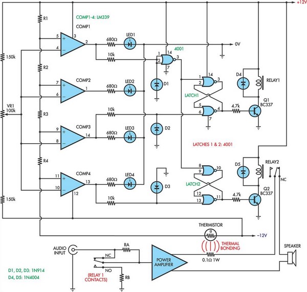
When the voltage on the non-inverting input of each comparator exceeds the voltage at its inverting input, the output transitions to a high state, activating the corresponding LED. NOR gate latches are connected to the outputs of the third...
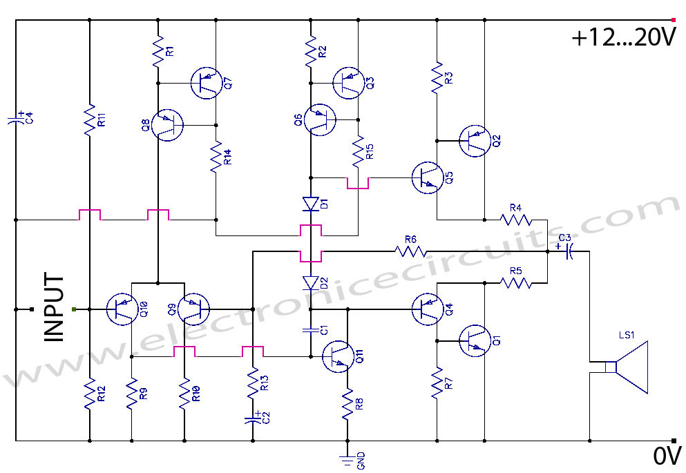
Discrete Class AB Transistor Audio Power Amplifier Circuit Diagram. This is a Class AB transistor power amplifier. It is a simple amplifier. The discrete Class AB transistor audio power amplifier is designed to provide efficient amplification of audio signals while...
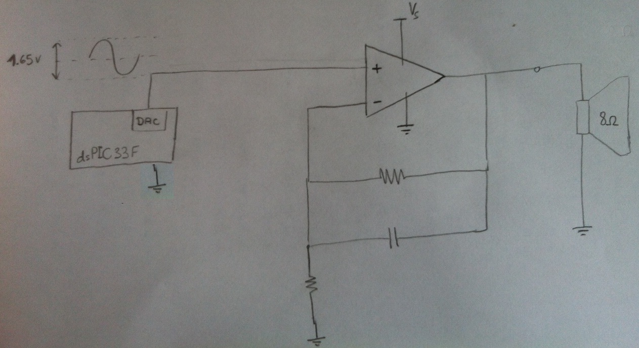
Design a circuit in which a microcontroller produces a signal and then uses an amplifier to drive an 8-ohm speaker. The LM386 has been used previously, but it cannot exceed 1W, which is insufficient. Additionally, a second-order anti-aliasing low-pass...
The major advantage of amplifiers of this type is that the normal static power dissipation is very low, and the overall power-conversion efficiency is high. Unfortunately, there are also some inherent disadvantages due to the intrinsic dissimilarity in the...
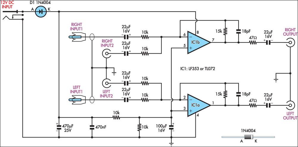
This circuit combines two separate line-level stereo (left and right) signals into a single stereo output, eliminating the need to switch between two sets of input signals. In this application, it is utilized to connect stereo audio from a...
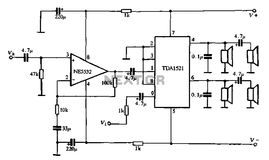
Active speaker with amplifier circuit TDA1521 and NE5532, featuring dual-channel input and dual-channel output. The active speaker circuit utilizes the TDA1521 integrated circuit, which serves as the power amplifier. This IC is designed for high-efficiency amplification, providing a robust output suitable...