
Active Low-Pass Rc Filter Circuit

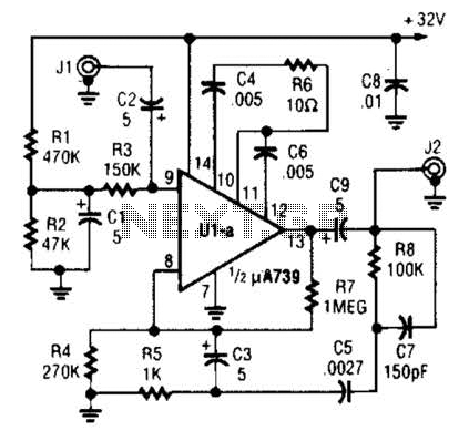
The circuit is designed as a filter, likely a low-pass or high-pass filter, where the cutoff frequency is determined by the values of the resistors and capacitors involved. The cutoff frequency (fc) can be calculated using the formula:
fc = 1 / (2πRC)
where R is the equivalent resistance and C is the equivalent capacitance in the circuit. By varying the values of R1, R2, C1, and C2, the cutoff frequency can be modified to meet specific application requirements.
For instance, if a lower cutoff frequency is desired, the values of R1 and R2 can be increased, or the values of C1 and C2 can be increased. Conversely, to achieve a higher cutoff frequency, the resistor values can be decreased or the capacitor values can be reduced.
In practical applications, this flexibility allows the circuit to be tailored for various tasks such as audio signal processing, where specific frequency ranges need to be filtered out or allowed through. The circuit may also include additional components such as operational amplifiers for signal conditioning, or diodes for protection against voltage spikes, depending on the complexity and requirements of the overall design.
The layout of the circuit should be carefully considered to minimize parasitic capacitance and inductance, which can affect the performance at higher frequencies. Proper grounding and shielding techniques should also be employed to ensure signal integrity.
In summary, this circuit's design provides a versatile solution for frequency filtering, with the ability to adjust component values to achieve the desired cutoff frequency, making it suitable for a wide range of electronic applications. The circuit shown has a cutoff frequency at about 1 kHz. Rl, R2, CI, and C2 can be scaled to change this to any other desired frequency.
Related Circuits
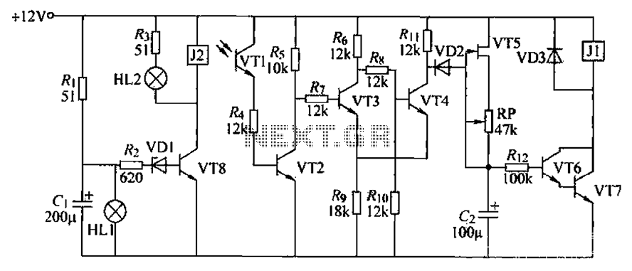
A blocking material monitoring circuit is presented. When the optical path is obstructed by the material, the phototransistor VT1 turns off, which subsequently turns off transistors VT2, VT3, and VT4. This arrangement is coupled to a flip-flop configuration. When...
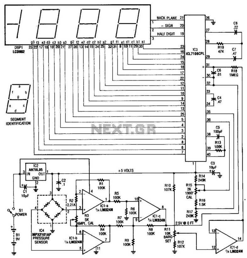
A pressure sensor (IC4) is utilized in conjunction with a DC amplifier to convert the bridge output from IC4 into a single-ended voltage. IC1 provides a reference voltage for setting the barometric pressure. IC3 is an A/D converter produced...
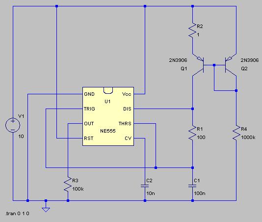
The typical BPM range for music is between 40 and 240 BPM, corresponding to periods of 1500 ms and 200 ms, respectively. A BPM of 120 equates to a period of 500 ms. The circuit requires a resistor R4...
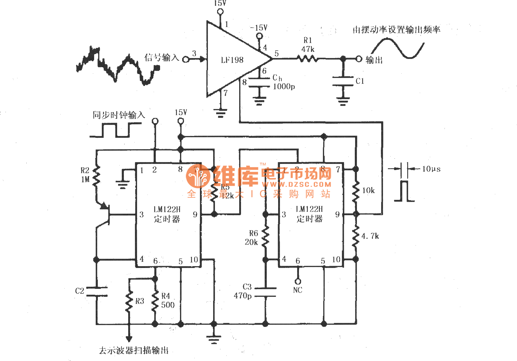
A synchronous clock signal is fed into a cascade of timer circuits composed of two LM122H devices. The synchronization clock is then converted into a pulse of the desired width, which is added to the LF198 logic end (pin...
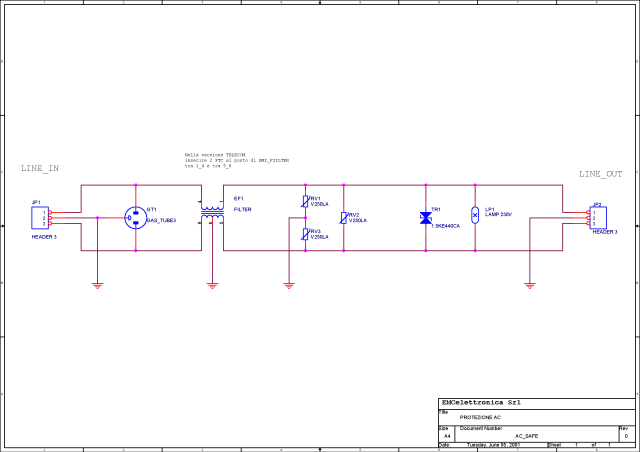
What is a circuit breaker? When is an AC power line filter or a phone line filter necessary? How can a noise filter be designed? Is it possible to create a homemade surge protector? The following circuit protection options...
A fundamental component for audio applications, this circuit functions as a general-purpose preamplifier. It is recommended to utilize two circuits for stereo configurations. This audio preamplifier circuit is designed to amplify low-level audio signals, making it suitable for a variety...