
timer Simple Metronome Circuit w/ Linear Pot Control

The circuit design revolves around generating a precise timing signal that corresponds to musical beats per minute (BPM). The operational amplifier (op-amp) is integral to this design, functioning as a comparator or amplifier that processes input signals to produce a clean output pulse. The timing is determined by the resistor-capacitor (RC) timing network, where the value of R4, when set to 14.5 MΩ, allows for the desired period of 500 ms to achieve a BPM of 120.
To adjust the resistance to the specified 5 kΩ, a 10 kΩ potentiometer can be utilized, enabling fine-tuning of the resistance value. This flexibility is crucial in applications where precise timing is essential, such as in metronomes or electronic drum machines.
The inclusion of a parallel transistor configuration serves a dual purpose: it reduces the effective resistance seen by the timing network, allowing for smaller physical resistor sizes, and it creates a current mirror with a 4:1 ratio. This current mirror stabilizes the control current, ensuring that it remains consistent relative to ground. This characteristic is particularly beneficial in designs where the op-amp is powered by varying supply voltages, as it enhances performance stability and reliability.
Overall, the combination of a carefully chosen resistor value, a tuning potentiometer, and a sophisticated transistor arrangement results in a robust circuit capable of producing accurate timing signals for musical applications.To get the usual BPM range for music of between 40 and 240 BPM, that corresponds to periods of 1500 ms and 200 ms respectively. A BPM of 120 is exactly 500 ms. As it is, the circuit would require an R4 of 14. 5 Mohm to yield a period of 500 ms (120 BPM). I need the value to be exactly 5K (10K pot in the center position). Here`s another version. That string of parallel transistors provides a 4:1 ratio step-down current mirror so that resistors can be smaller. It also makes the control current relative to ground which is nice depending on how you power your op amp.
🔗 External reference
Related Circuits
This circuit is appropriate for any scenario where over-current protection is necessary. An example from the model train hobbyist community illustrates its importance. Experienced model train enthusiasts understand that locating the source of a short circuit can be quite...
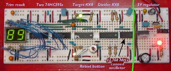
One of the nicest features of the 8-bit KX8 microcontroller (manufactured by Freescale Semiconductor) is that it includes an internal clock generator (ICG). This allows the chip to run without the trouble and expense of an external crystal or...
This light sensor switch circuit enables the automatic activation of a lamp when ambient light levels are low (such as during nightfall) and keeps the lamp illuminated for a specified duration. When transistors T4 and T5 are activated, the...
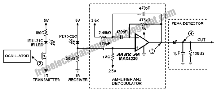
The following circuit illustrates an Infrared Proximity Sensor Circuit Diagram. This circuit is based on the MAX4230 integrated circuit. Features include a 10 kHz oscillator. The Infrared Proximity Sensor Circuit utilizing the MAX4230 integrated circuit is designed to detect the...
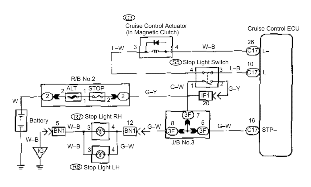
When the brake pedal is depressed, battery positive voltage normally applies through the STOP fuse and stop light switch to terminal STP of the ECU, and the ECU turns the cruise control off. A failsafe function is provided so...
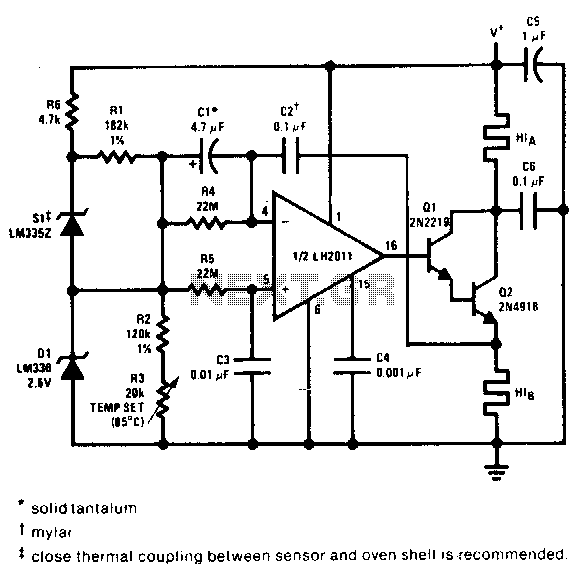
This proportional control crystal oven heater utilizes lead/lag compensation to achieve rapid setting. The time constant can be adjusted using resistor R4 and the compensating resistor R5. It is advisable to use a regulated supply for Q2 if it...