
AD Design

The right leg driver circuit plays a crucial role in biomedical applications, particularly in electrocardiogram (ECG) systems, where it helps eliminate noise and interference from the signal being measured. The circuit achieves this by summing and inverting the common mode signals from multiple amplifier boards, effectively reducing the common voltage present in the system. The output is then fed back to the patient's body, often through a point such as the earlobe, which serves as a reference ground.
In addition to its primary function, the circuit includes a level converter that bridges the communication gap between components operating at different voltage levels. The A-D converter outputs a digital signal at 3 volts, while the microcontroller is designed to operate at 5 volts. The level converter ensures that signals can be accurately transmitted between these components without risk of damage or data loss due to voltage mismatches.
The design of the right leg driver circuit typically incorporates operational amplifiers configured for summation and inversion, along with passive components such as resistors and capacitors to filter and stabilize the signals. The level converter may utilize a dedicated IC or a simple transistor-based design to shift the voltage levels appropriately. Overall, this circuit is essential for maintaining signal integrity in sensitive electronic systems where accurate measurements are critical.The right leg driver circuit is where many amplifier board circuits common signals are summed and inverted though the Right Leg Driver circuit & sent back to the body to cancil out common voltages. This ground point could be a ear lobe. Their also is a 3 Volt to 5 Volt level converter that is to communicate between the A-D converter that outputs 3
volts digital and the microcontroler that runs at 5 volts. 🔗 External reference
Related Circuits

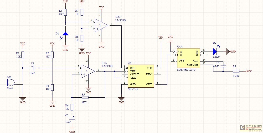
The input capacitor is used for low-frequency cut-off, with a standard value of 0.1 µF, resulting in a cut-off frequency of approximately 16 Hz. The input capacitor plays a critical role in electronic circuits, particularly in signal processing and audio...
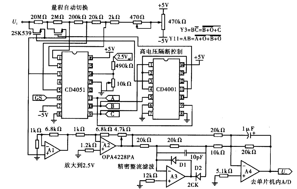
Voltage measurement is a fundamental aspect of electronic technology today, with increasing demands for accuracy and functionality in instruments. This is particularly critical when measuring signals with significant phase differences, as it is essential to ensure the accuracy of...
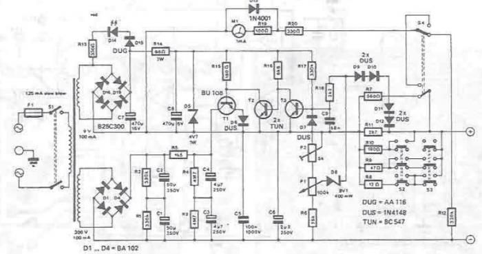
A DC power supply can be designed using high voltage transistors to provide an adjustable supply voltage ranging from 10 to 300 volts, which can be modified with potentiometer P1. Transformers used in these power supplies typically feature multiple...
The optically-controlled circuit plays a crucial role in urban street lighting and corridor illumination. By utilizing this circuit, lighting lamps can be automatically turned on and off based on ambient light levels, thereby reducing the need for manual control,...

The LTC3113 fixed frequency buck-boost DC-DC converter can be utilized to design various power supply circuits that operate with input voltages that are above, below, or equal to the output voltage. The topology integrated into the IC ensures low...

Transistors are essential components of electronic circuits. The success of a circuit design depends on the selection of the appropriate transistor type and the calculations involved. Transistors serve as fundamental building blocks in electronic circuits, playing critical roles in amplification,...