
TDA7384 class AB Audio Power Amplifier circuit design electronic project

The input capacitor plays a critical role in electronic circuits, particularly in signal processing and audio applications. Its primary function is to block direct current (DC) while allowing alternating current (AC) signals to pass. The cut-off frequency, which is determined by the capacitor's value and the resistance in the circuit, defines the lowest frequency that can effectively pass through the capacitor.
For a capacitor value of 0.1 µF, the cut-off frequency can be calculated using the formula:
\[ f_c = \frac{1}{2 \pi R C} \]
where \( f_c \) is the cut-off frequency in hertz (Hz), \( R \) is the resistance in ohms (Ω), and \( C \) is the capacitance in farads (F). In this scenario, with a standard capacitor value of 0.1 µF, the cut-off frequency is approximately 16 Hz when used with a resistance of about 100 kΩ.
This low-frequency cut-off is particularly significant in audio circuits, where it helps to eliminate unwanted low-frequency noise and DC offsets, ensuring that only the desired audio signals are amplified or processed. The choice of a 0.1 µF capacitor is common in many applications due to its balance between size, performance, and cost. It is essential to select a capacitor with a suitable voltage rating and type (such as ceramic or film) to ensure reliability and performance in the intended application. Additionally, the characteristics of the capacitor, including its equivalent series resistance (ESR) and temperature coefficient, may influence the overall performance of the circuit, particularly in high-frequency applications.The input capacitor is for the low frequency cut-off and the standard value for the input capacitors is 0. 1uF ( the cut-off for this value is amount to 16Hz). 🔗 External reference
Related Circuits
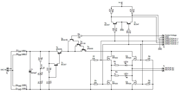
The K8000 DAC High Power Amplifier is an electronic amplifier with an adjustable output voltage ranging from 0 to 9 V and capable of delivering an output current of up to 9 Amperes. The K8000 DAC High Power Amplifier is...
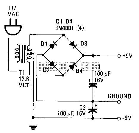
This power supply provides both +9 V and -9 V outputs to replace two 9-V batteries. The rectifier circuit consists of two separate full-wave rectifiers, each connected to the secondary winding of the transformer. The first full-wave rectifier, made...
With a 1.5V battery supply, the integrated circuit LM3909 can drive the light-emitting diode NSL5027. The 300μF electrolytic capacitor acts as a timing capacitor, which limits the flash speed to approximately 1Hz. The circuit utilizes the LM3909, a popular LED...
This 18 dB gain amplifier was constructed using the Manhattan-style technique to assess the Linear Technology LT1253 dual video amplifier as a potential output amplifier for Direct Digital Synthesis (DDS) systems that utilize the Analog Devices AD9850 and similar...
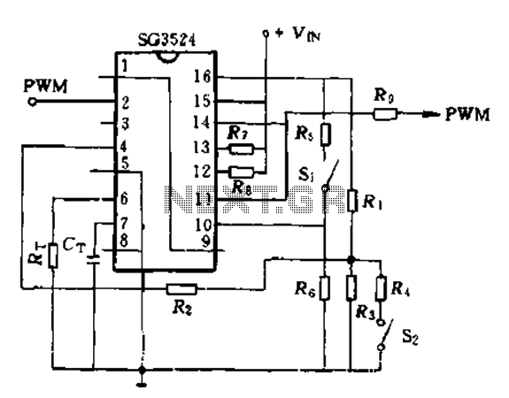
The SG3524 is utilized solely as a pulse width modulator. The error amplifier is configured in a follower arrangement. As illustrated in Figure 10-7, the ACR output connects to PWM output pin 2, which serves as the control signal....
Charging a mobile phone or cellphone battery presents a significant challenge while traveling, as a power supply source is often not readily available. If the cellphone remains switched on continuously, its battery can deplete within five to six hours,...