
Adding a Mono Mic or Tape Level Output to the 302

The circuit described integrates a mono microphone-level output into an existing audio system, specifically designed for the 302 model. The primary function of this modification is to facilitate the connection of devices that require a mono mic-level input, such as transcription recorders and wireless transmitters.
The circuit operates by summing the left and right tape outputs, which are typically at line level, and attenuating this combined signal to a mic-level output. The attenuation is set to -55 dB, which is standard for microphone inputs, ensuring compatibility with various audio devices that expect a lower input level.
The design includes a summing amplifier configuration that takes the left (L) and right (R) outputs from the tape deck. These signals are fed into a resistor network that combines them into a single output. The resistors are selected to achieve the desired attenuation while maintaining a balanced input from both channels.
Furthermore, the circuit design allows for the tape output to remain available for other auxiliary inputs, which is crucial for setups where multiple devices may need to access the original tape signal without interference.
In scenarios where it is necessary to keep the output at tape level, the circuit can be adjusted to bypass the attenuation stage, allowing users to select between a mono output at mic level or a stereo output at tape level. This flexibility is particularly useful for live sound environments or recording applications where the audio routing may change frequently.
The accompanying wiring diagram is essential for accurately implementing this modification, providing clear connections for the tape outputs and the summing circuit. Properly following this schematic will ensure that the mono mic-level output functions effectively while maintaining the integrity of the original tape output for other uses.The addition of a mono mic-level output to the 302 is a useful addition for feeding transcription recorders, Comtek transmitters, and other inputs. The diagram below illustrates the proper wiring to add a mono mic-level output from the tape level output.
This circuit sums the left and right tape outputs and attenuates the summed signal to Mic l evel (-55 dB below Line level). It also passes the tape output through to be used for other aux inputs. In some instances it may be useful to keep the output level at tape but some the left and right stereo signal to mono. The diagram below illustrates the proper wiring to sum the left and right stereo signal to a mono signal while keeping the output at tape level.
🔗 External reference
Related Circuits
The micropower circuit automatically provides shutdown, power-up, and low-battery lockout functions without requiring software or operator control. The micropower circuit is designed to manage power efficiently in battery-operated devices, ensuring optimal functionality while conserving energy. The shutdown feature is activated...

This circuit maintains a constant voltage, with an adjustable output voltage. It serves to reduce the input voltage while keeping the voltage constant. The amplifier model used is the Q1 2N3904 in a common-emitter configuration. This configuration allows the...
This water level alarm circuit can be utilized as a water level indicator to monitor the desired water level in various applications, such as tanks, swimming pools, or any location where water is stored. The circuit is constructed using...
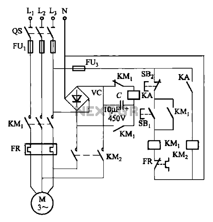
The circuit depicted in Figure 3-137 eliminates the need for a step-down transformer by utilizing the principle of energy storage capacitor discharge for braking. It can be employed to transform the power of motors with a rating of less...
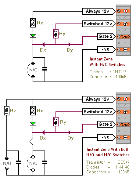
The SCR Burglar Alarm System allows for the addition of multiple extra zones. The primary circuit is designed for typical normally-closed input devices, including magnetic reed contacts, micro switches, foil tape, and passive infrared (PIR) sensors. An additional circuit...
This circuit monitors the charging process of a 12 Volt Lead Acid or Tubular battery. The LED status indicates whether the battery is charging and signals when it reaches a full charge. It can be integrated into various battery...