
water level alarm using 555 ic

The water level alarm circuit employing the 555 timer IC operates in a monostable or astable mode, depending on the design requirements. In the monostable configuration, the circuit can be triggered when the water level reaches a predetermined point, sending an alert signal. Conversely, in the astable mode, the circuit can continuously monitor the water level, providing real-time feedback.
Key components of the circuit include the 555 timer IC, resistors, capacitors, and a water level sensing mechanism, typically consisting of conductive probes or float switches. The probes are placed at specific heights within the tank or container, allowing the circuit to detect the presence or absence of water at those levels. When water comes into contact with the probes, it completes the circuit, triggering the 555 timer to activate an alarm or indicator light.
The alarm can be implemented using a buzzer or LED, which provides a visual or audible alert when the water level exceeds or drops below the set point. Additional features may include adjustable sensitivity through variable resistors, allowing customization based on the specific application or environment.
Power supply considerations are essential for the circuit's operation, with options for battery or mains power, depending on the installation setting. Proper layout and component selection are critical to ensure reliable performance and minimize false alarms due to environmental factors such as splashing water or electrical noise.
Overall, this water level alarm circuit is a practical solution for monitoring water levels in various settings, enhancing safety and convenience by providing timely alerts for users.You can use this water level alarm circuit anywhere as a water level indicator to detect the desired level of water for example in tanks, swimming pools or at any place where you store water. The circuit is build around a 555 timer IC which is a famous and well know IC and you can easily get it.
🔗 External reference
Related Circuits
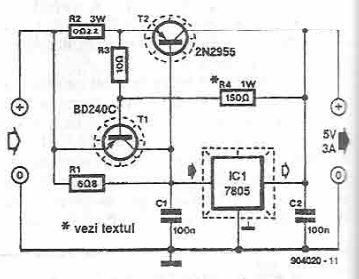
This power supply circuit is designed to provide a high current 5-volt output using a 7805 voltage regulator along with several standard electronic components. The transistor T1 functions as a current limiter. When the voltage across resistors R2 and...
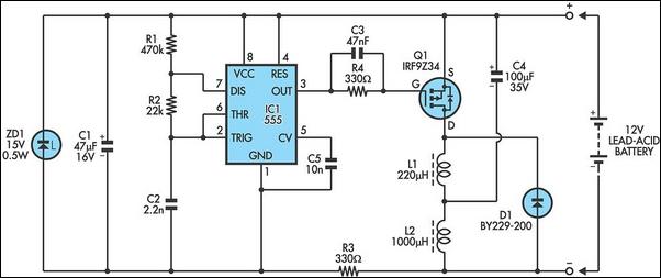
The following circuit illustrates a 6/12/24V Lead Acid Battery Charger Circuit Diagram. Features: It is essentially a high-voltage pulse generator. The circuit diagram for a 6/12/24V Lead Acid Battery Charger is designed to efficiently charge lead-acid batteries of varying voltages....
In this project, an embedded system is designed for tracking and positioning vehicles using the Global Positioning System (GPS) and Global System for Mobile Communications (GSM). The AT89S52 microcontroller interfaces with various hardware peripherals. The system continuously monitors a...
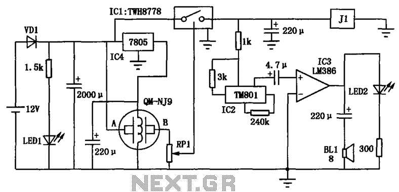
The alcohol detection alarm controller circuit is illustrated in the figure. It utilizes the QM-NJ9 alcohol gas sensor, which detects the presence of alcohol vapors. When alcohol is detected, the resistance between the AB-QM-NJ9 decreases, causing the wiper of...
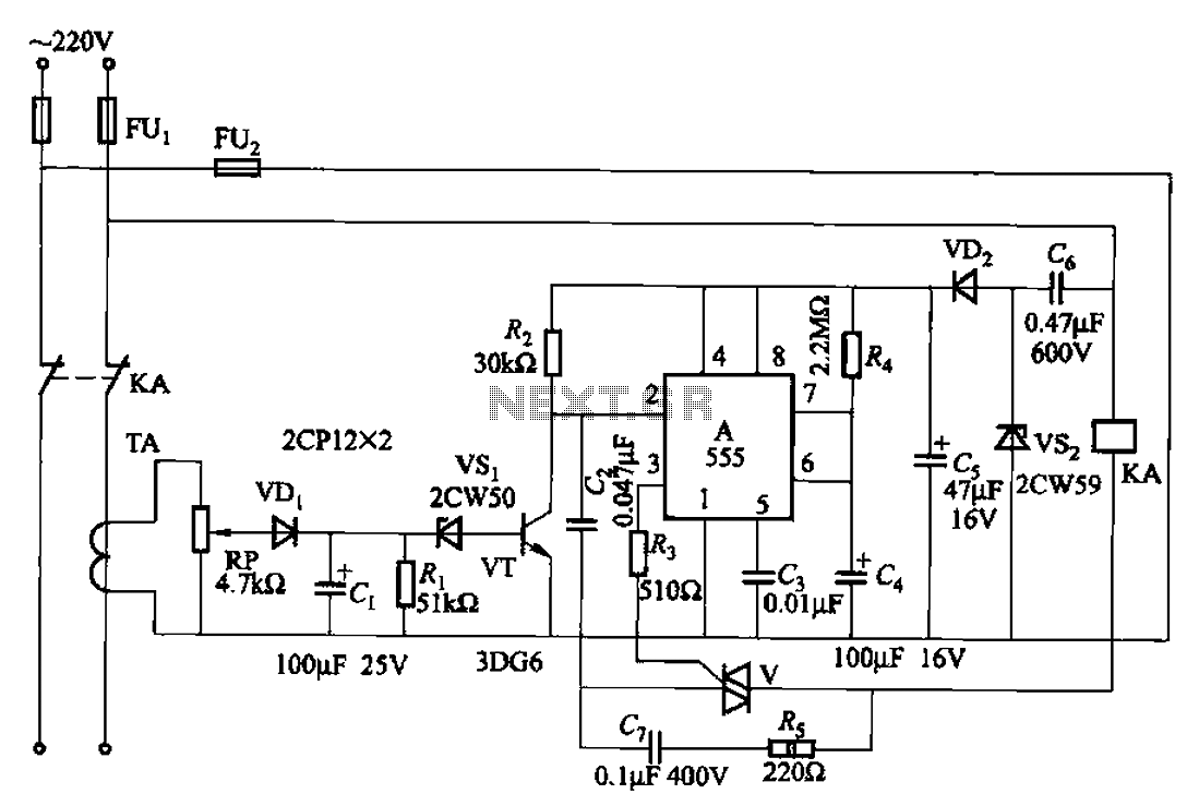
The 555 limit circuit, which is an integrated electrical circuit, is designed to manage large electrical loads. It automatically disconnects power when the load exceeds a predetermined threshold. Once the load is reduced below this threshold, power is restored...
The address bits in the encoder are unconnected, while they are grounded in the decoder. It is advisable to connect them to ground in the encoder as well. Additionally, when the keys in the transmission circuit are open, the...