
Adding VU Meter to Dantimax thatmic preamp

The integration of a VU meter with the Dantimax mic preamp can enhance audio monitoring by providing visual feedback on signal levels. To achieve this, a schematic design must be developed to connect the VU meter to the output of the mic preamp.
The VU meter typically requires a DC voltage for operation, which can be obtained from the preamp's power supply. The connection should be made to the output stage of the mic preamp, where the audio signal is present. It is crucial to ensure that the output signal is appropriately scaled, as VU meters usually operate on a specific voltage range.
A resistor divider network may be employed to scale down the output voltage to a level suitable for the VU meter. A capacitor can also be added in parallel to smooth out the signal, providing a more stable reading on the meter. Additionally, a protection diode may be necessary to prevent reverse polarity or voltage spikes from damaging the VU meter.
The schematic should include the mic preamp output, the resistor divider, the VU meter connections, and any additional components such as capacitors and diodes. Proper grounding and shielding techniques should be implemented to minimize noise and interference in the audio signal path.
Consulting the VU meter's datasheet will provide specific connection details, including the required input voltage and current specifications, ensuring compatibility with the mic preamp output.Hi all, i`ve recently bought the dantimax thatmic pre amp and i was wondering if anyone could point me in the right direction to install a vu meter.. 🔗 External reference
Related Circuits

The Kelvin scale version reads from 0 to 1999 K theoretically, and from 223 K to 473 K actually. The 26 kΩ resistor brings the input within the ICL7106 common-mode voltage range; two general-purpose silicon diodes or an LED...
Understanding the concept of hysteresis is crucial. Generally, this phenomenon leads to losses observed in the dielectric of a capacitor or the lamination of a transformer, which can manifest as heat (emission of infrared photons). Alternatively, it can extract...
The following two-transistor circuit is a preamplifier for magnetic phono cartridges, characterized by its frequency response defined by the RIAA standard for phono recording. This preamp circuit has a gain of approximately 40 dB (midband) at 1 kHz. The...
This meter circuit utilizes a single integrated circuit (IC) and a minimal number of external components. It displays audio levels using ten light-emitting diodes (LEDs). The input voltage can range from 12V to 20V, with a recommended voltage of...
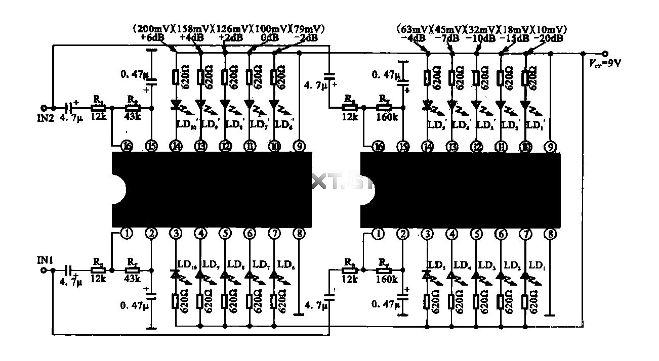
The circuit consists of dual drive integrated circuits (ICs) utilized in a 10 LED level meter configuration. The schematic features two TLM8101 driver ICs, which can be employed as alternatives. The 10 LED level meter circuit is designed to provide...
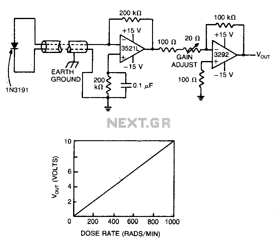
A commercial diode serves as the detector in this highly accurate radiation monitor. The low-drift FET-input operational amplifier amplifies the detector current to a usable level, while the chopper-stabilized amplifier provides additional gain, minimizing errors caused by fluctuations in...