
Dual drive ICs 10LED level meter circuit

The 10 LED level meter circuit is designed to provide a visual representation of voltage levels through the illumination of LEDs. In this circuit, the dual drive ICs play a crucial role in controlling the LEDs based on the input voltage levels. The TLM8101 is a versatile driver capable of managing multiple LEDs, making it suitable for this application.
The circuit typically operates by receiving an analog input voltage, which is then compared against predefined thresholds. As the input voltage varies, the corresponding LEDs illuminate sequentially, indicating the level of the input signal. Each LED corresponds to a specific range of voltage, and the dual drive configuration allows for more efficient control and reduced power consumption.
The TLM8101 ICs can be configured for different driving capabilities, allowing flexibility in the number of LEDs that can be lit simultaneously. The design may include resistors to limit the current through the LEDs, ensuring they operate within safe limits. Additionally, capacitors may be used for smoothing any fluctuations in the input signal, providing a more stable output.
For implementation, it is essential to consider the power supply requirements of the TLM8101 and the forward voltage ratings of the LEDs used. Proper heat dissipation methods should also be applied to prevent overheating during operation. Overall, this dual drive LED level meter circuit is an effective solution for visualizing voltage levels in various electronic applications.Dual drive ICs 10LED level meter circuit Dual-drive IC is shown in the IO LED level meter circuit, the figure of two TLM8101 driver IC can also be used instead.
Related Circuits
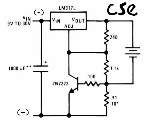
This is a straightforward charger designed for 9V to 30V batteries, primarily operated by the IC LM317L and a 2N222 transistor. It utilizes direct input DC voltage, and a recommended capacitor of 1000µF is included for filtering the output...
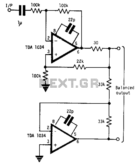
This circuit will handle +24 dBm with ± 12 volts supply using TDA 1034s. This circuit uses current and voltage feedback. The described circuit utilizes the TDA 1034S integrated circuit, which is designed for audio applications and can handle an...
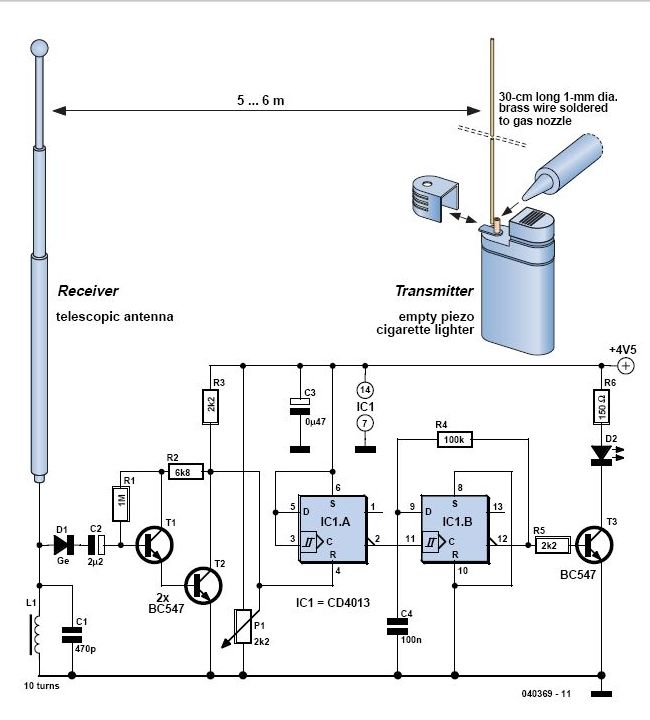
In 1896, Marconi successfully transmitted electromagnetic waves over a distance of approximately 3 kilometers. Shortly thereafter, he established radio communication across water between Lavernock Point in South Wales and Flat Holm Island. The transmitter utilized a spark inductor connected...
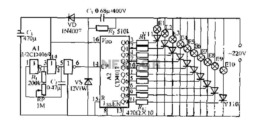
The digital integrated circuit consists of a controller for a string of ten road flashing lights, which drives the El-El0 string lights in a flashing cycle. The system utilizes a ten-count decoder, specifically the CD4017 digital integrated circuit. When...
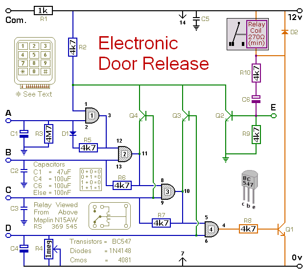
This circuit is designed to operate an electrical door-release mechanism, but it can also be utilized for other applications. When the user enters a four-digit code of their choice, the relay will energize for a preset time period. The...
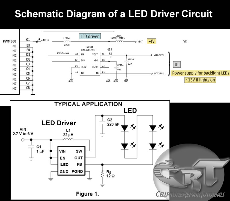
An LED (light-emitting diode) is utilized to illuminate keypad keys and LCD screen displays on all mobile phone handsets. It is controlled by the voltage or current drawn at its terminals. In the schematic diagram, the LEDs are driven...