
Adjustable 3 Ampere Regulator

The circuit combines the 78L05 voltage regulator, which provides a stable output voltage, with the TDA2030 audio amplifier, which enhances the current capability of the system. The 78L05 regulates the voltage to a fixed output of 5 V, while the TDA2030 can be configured to output higher voltages, making it suitable for various applications requiring adjustable power supplies.
The two potentiometers play a crucial role in the voltage adjustment mechanism. Potentiometer P1 serves as a coarse adjustment for the output voltage, allowing the user to set a maximum output level. Trimpot P2, on the other hand, allows for fine-tuning of the output voltage, enabling precise control. This dual-potentiometer setup is advantageous in applications where specific voltage levels are critical.
Capacitors included in the circuit are essential for stabilizing the output voltage and filtering any noise that may affect the performance of the regulator. Proper selection of capacitor values ensures that the circuit operates efficiently across different load conditions.
Thermal management becomes critical when the output current exceeds 1 A. The TDA2030 is designed to handle moderate power levels, but as the power dissipation increases, a heatsink is recommended to prevent overheating and ensure reliable operation. The heatsink should be sized appropriately based on the expected load and ambient conditions.
This adjustable voltage regulator circuit is ideal for powering various electronic devices that require a stable and adjustable power source. Its simplicity and robustness make it suitable for both prototyping and practical applications in electronic projects.By combining a common 78L05 with an integrated audio amplifier of the type TDA2030, an adjustable voltage regulator can be constructed in a very simple manner that works very well. The output voltage is adjustable up to 20 V, with a maximum current of 3 A. Since the TDA2030 comes complete with a good thermal and short-circuit protection circuit, t his adjustable regulator is also very robust. As illustrated by the schematic, the design of this circuit is characterized by simplicity that is hard to beat. In addition to the two ICs, the regulator contains actually only two potentiometers and a few capacitors.
The adjustment is done by ¬rst turning potentiometer P1 to maximum (wiper to the side of the 78L05) and subsequently turning trimpot P2 until the desired maximum output voltage is reached. P1 is then used to provide a continuously adjustable voltage between this maximum and nearly zero volts.
At relatively small output currents there are no specific requirements regarding the cooling. However, when the output current exceeds 1 A, or if the input to output voltage difference is quite large, the amplifier IC has to dissipate too much power and a small heatsink is certainly appropriate. 🔗 External reference
Related Circuits
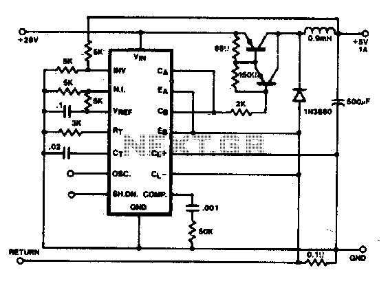
In this conventional single-ended regulator circuit, the two outputs of the SG1524 are connected in parallel for effective 0-90% duty-cycle modulation. The use of an output inductor requires an RC phase compensation network for loop stability. The described circuit utilizes...
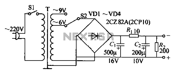
The adjustable current power supply circuit operates at 6V and 9V, utilizing a minimal number of components, which facilitates easy assembly. The circuit can deliver an adjustable output current of up to 100mA, serving as a suitable alternative to...
There are two regulator circuits that utilize the L200 integrated circuit from SGS-Thomson to regulate voltage and current. In circuit Fig. 1, the output voltage can be adjusted using the variable resistor RV1. In Fig. 2, both output voltage...
There will be many occasions when it is beneficial to utilize the P05 supply module sourced from a higher voltage supply. For instance, this could be advantageous when integrating balanced inputs. The P05 supply module is designed to facilitate the...
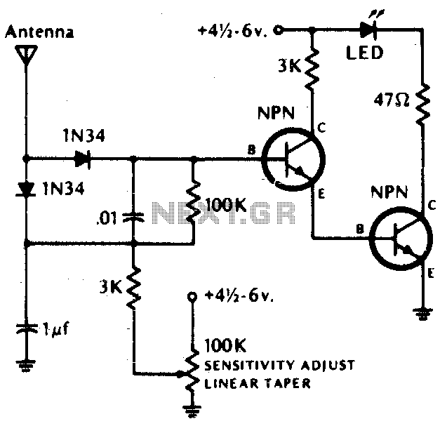
The LED illuminates when the RF field exceeds the pre-set field strength level. Germanium diodes are recommended. Additional information: Transistors (NPN) include 2N2222, 2N3393, 2N3904, or equivalent. The circuit described is a simple RF field strength indicator that utilizes an...
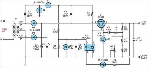
This circuit is a MOSFET-based linear voltage regulator with a voltage drop as low as 60mV at 1A. It utilizes a 15V-0-15V transformer and an IRF540 N-channel MOSFET (Q1) to deliver a regulated 12V output. The required gate drive...