
Single-ended regulator

The described circuit utilizes the SG1524, a versatile pulse-width modulation (PWM) controller, to achieve efficient voltage regulation. By connecting the two outputs of the SG1524 in parallel, the circuit is capable of modulating the duty cycle from 0% to 90%, allowing for a wide range of output voltage adjustments. This modulation is critical in applications where precise voltage levels are required, such as in power supplies for sensitive electronic devices.
The inclusion of an output inductor is essential for energy storage and smoothing the output voltage. The inductor works in conjunction with the output capacitor to filter the PWM signal, resulting in a more stable and less rippled output voltage. However, the presence of the inductor introduces phase shifts in the feedback loop, which can lead to instability if not properly compensated.
To ensure loop stability, an RC phase compensation network is implemented. This network typically consists of a resistor (R) and a capacitor (C) connected in a specific configuration to adjust the phase response of the feedback loop. The resistor is placed in series with the feedback path, while the capacitor is connected to ground. This arrangement helps to counteract the phase lag introduced by the inductor, thus enhancing the stability of the regulator circuit.
In summary, the combination of the SG1524's parallel outputs, output inductor, and an RC phase compensation network forms a robust single-ended regulator circuit capable of delivering stable output voltage across a range of duty cycles. Proper design and implementation of these components are crucial for achieving optimal performance and reliability in various electronic applications.In this conventional single-ended regulator circuit, the two outputs of the:SG1524 are connected in parallel for effective 0-90% duty-cycle modulation The use of an output inductor requires an RC phase compensation network for loop stability.
Related Circuits
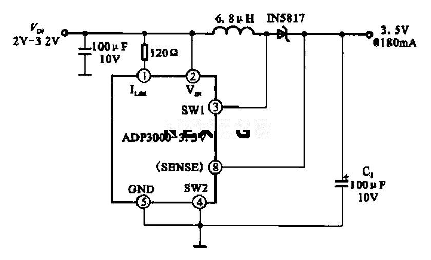
Boost 3.5V regulator circuit. This chip can boost or create a stable voltage supply from approximately 3V DC to a DC voltage of 3.5V. The boost regulator circuit is designed to increase a lower DC voltage, specifically from around 3V...
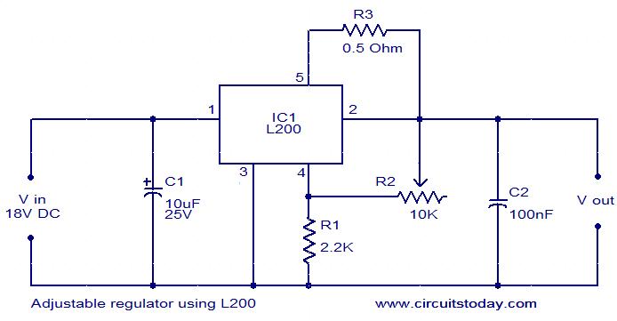
The circuit diagram depicts an adjustable voltage regulator utilizing the IC L200. The L200 is a monolithic integrated adjustable voltage regulator IC that incorporates features such as current limiting, thermal shutdown, power limiting, and input over-voltage protection. This regulator...
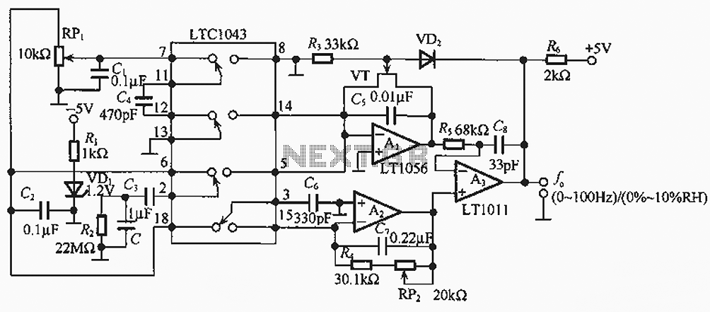
The humidity/frequency conversion circuit operates similarly to the previously mentioned humidity sensors. At a humidity level of 76%, the equivalent capacitance is 500 pF, with a capacitive relative humidity variation rate of +1.7 pF/%. The circuit includes an integrating...
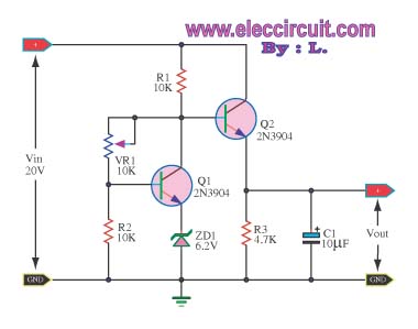
This circuit maintains a constant voltage, with an adjustable output voltage. It serves to reduce the input voltage while keeping the voltage constant. The amplifier model used is the Q1 2N3904 in a common-emitter configuration. This configuration allows the...
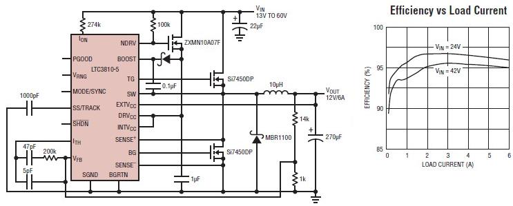
The LTC3810-5 synchronous step-down switching regulator controller allows for the design of a straightforward 12-volt switching power supply electronic project with minimal external components. This controller can directly reduce voltages from up to 60V, making it suitable for telecommunications...
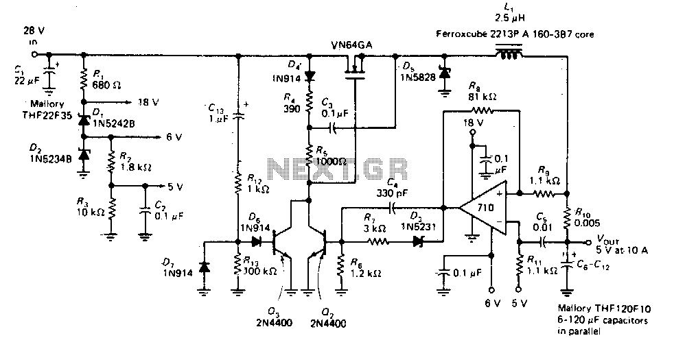
This circuit provides a regulated DC output with less than 100 mV of ripple for microprocessor applications. The required operating voltages are derived from a bleeder resistor network connected across the unregulated 28 V supply. The output of the...