
Adjustable Attenuator for Oscilloscope

The described input attenuator circuit employs a commutating capacitor mechanism to effectively mitigate the input capacitance associated with the Field Effect Transistor (FET) buffer. This is particularly crucial for maintaining the performance of the DC-10 MHz amplifier, as excess input capacitance can adversely affect the frequency response and overall signal integrity.
In this circuit, the commutating capacitors are strategically implemented to ensure that they counterbalance the input capacitance, thereby stabilizing the input signal across the specified frequency range. The input resistance is maintained at a consistent level of 1 MΩ across all range settings, which is essential for ensuring that the circuit operates within the desired parameters regardless of the selected sensitivity scale.
The design mandates that all resistive components be selected to achieve this 1 MΩ input resistance, while also considering the ratios of these resistances. This ratio is critical as it determines the scale sensitivities, allowing the circuit to correctly attenuate the input signals according to the specified settings. Careful selection and arrangement of these resistors will enable the attenuator to provide accurate and reliable performance across its operational range.
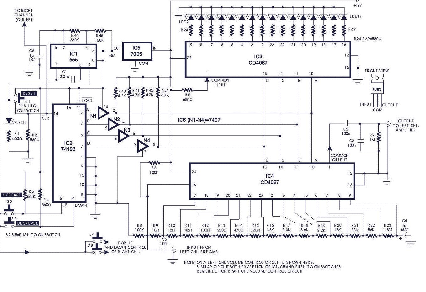
Overall, the integration of commutating capacitors in conjunction with precisely chosen resistive elements forms a robust input attenuator design that is well-suited for applications requiring high-frequency signal processing while maintaining optimal input impedance characteristics.The input attenuator uses a commutating capacitor to cancel the input capacitance of the FET buffer (see DC-10 MHz amp schematic). The commutating capacitors are absolutely necessary to cancel the effect of the input capacitance to the DC-10MHz amplifier.
The theory of the commutating capacitors will not be discussed here. The input resistance is 1M ohm at all range settings. All resistances should be chosen to provide 1M ohms at any scale sensitivity. However the ratio of the resistances should also be chosen to provide the scale sensitivities shown below. 🔗 External reference
Related Circuits
Motor potentiometers are not preferred, particularly when inexpensive and compact attenuators are used with large motors. However, larger blue Alps potentiometers, such as those found on eBay, are favored. Motor potentiometers serve as variable resistors that control the speed or...
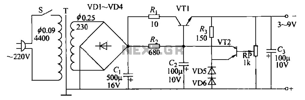
A 3-9V adjustable 100mA power supply is presented, featuring a series regulator circuit that utilizes amplifier tubes. The output voltage can be continuously adjusted between 3V and 9V, with a maximum output current of 100mA, making it suitable for...
This current-limiting circuit, illustrated as part of a small bench power supply, can be utilized with any dual-rail current source. The section of the circuit to the left limits the current at the input to the dual voltage regulator...
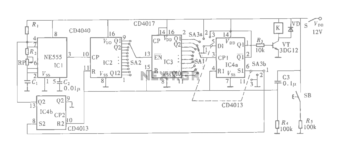
The multifunction circuit primarily refers to its capability to operate in three modes: "delayed pull," "time release," and "delayed cycle." The term "delay" indicates that the relay is energized after a predetermined time; however, the relay does not activate...
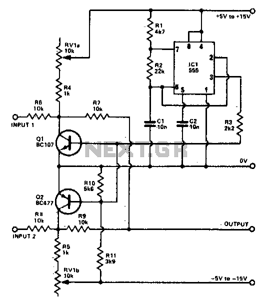
The foundation of the beam splitter utilizes a 555 timer configured as an astable multivibrator. Signals at the two inputs are alternately displayed on the oscilloscope, exhibiting a distinct separation between them. The output is regulated by the tandem...
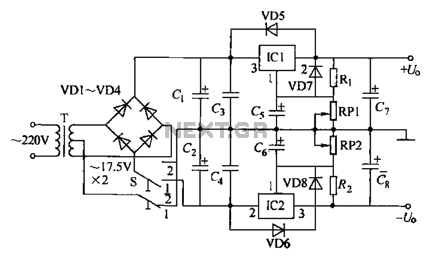
The circuit utilizes a three-terminal adjustable integrated voltage regulator. It includes a gear set and a power supply voltage that is stepped down using a transformer rated at 17.5V x 2 AC. The output voltage after the bridge rectifier...