
Beam sputter for oscilloscope

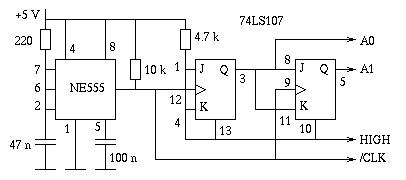
The circuit design incorporates a 555 timer integrated circuit (IC) configured in an astable mode, which allows it to generate continuous square wave signals. This configuration is essential for creating a beam splitter effect, where the input signals are processed to produce alternating outputs. The 555 timer's frequency and duty cycle can be finely tuned by adjusting the resistors and capacitors connected to it, allowing for precise control over the timing characteristics of the output signals.
In this setup, two input signals are fed into the 555 timer, which processes them to produce two distinct output waveforms. These outputs can be observed on an oscilloscope, where they appear as clearly separated traces, making it easy to analyze the timing and phase relationship between the two signals. The separation is crucial for applications that require the simultaneous observation of two different signal sources without interference.
The tandem potentiometer KVla/b plays a vital role in this circuit by allowing for real-time adjustments to the output amplitude. By varying the resistance, the user can control the voltage levels of the output signals, thus modifying the height of the traces displayed on the oscilloscope. This feature is particularly useful in experimental setups where signal strength may need to be optimized for better visibility or analysis.
Overall, this configuration of a 555 timer as an astable multivibrator, combined with the adjustable potentiometer, provides a versatile and effective solution for signal processing and analysis in various electronic applications. The ability to visualize and manipulate multiple signals simultaneously enhances the functionality of the circuit, making it suitable for both educational and practical uses in electronics.The basis ofthe beam splitter is a 555 timer connected as an astable multivibrator. Signals at the two inputs are alternately displayed on the oscilloscope with a clear separation between them The output is controlled by the tandem potentiometer KVla/b which also varies the amplitude of the traces.
Related Circuits
A few months ago as I was surfing on the net, I saw an oscilloscope based on PIC18F2550 microcontroller and a KS0108 controller based graphical LCD. That was Steven Cholewiak's web site. I had never seen before so amazing...
The project involves the design of a custom multiplexer for a four-channel oscilloscope, allowing for simultaneous display of multiple figures with distinct X/Y inputs. The instrument is intended to enhance the functionality of existing oscilloscopes, particularly in conjunction with...

The general (and very basic) principle of operation is shown in Figure 1. The test signal is simply derived from the mains, and is a sinewave at 50 or 60Hz. In most locations, the sinewave will be distorted, but...
The circuit below provides the horizontal drive voltage. The supply voltage on one end, +135 to +165, is made variable for the horizontal position control. The described circuit is designed to generate a horizontal drive voltage, which is essential in...
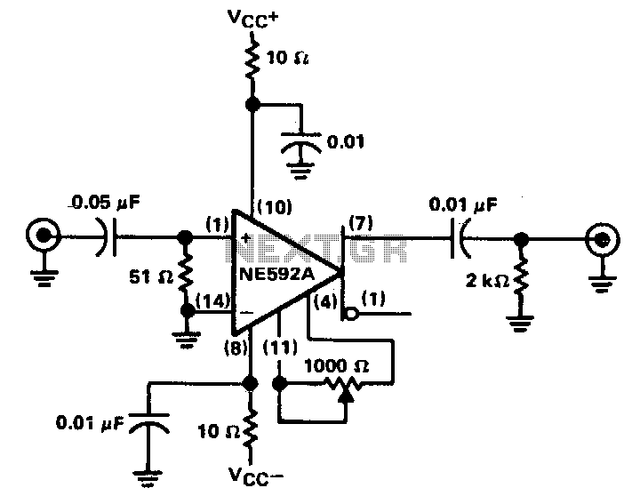
The circuit provides a voltage gain of 20 ±0.1 dB within a frequency range of 500 kHz to 50 MHz. The low-frequency response of the amplifier can be enhanced by increasing the value of the 0.05 µF capacitor connected...
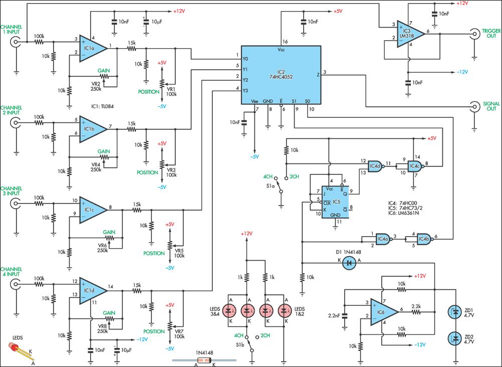
This circuit allows for the simultaneous display of four signals using a single channel of an oscilloscope. It sequentially switches each input to the output with some signal processing in between. It is designed for low-frequency signal measurements and...