
Adjustable output MAX761 boost power supply

The MAX761 is a high-efficiency DC-DC boost converter designed to convert a lower input voltage to a higher output voltage while maintaining low power consumption. This device is particularly useful in battery-operated applications where energy efficiency is paramount.
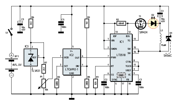
The output voltage (Vo) is adjustable and is set by the external resistors R1 and R2. The formula Vo = VREF (1 + R2/R1) indicates that the output voltage is a function of the reference voltage (VREF), which is fixed at 1.5V in this configuration. The choice of R1 and R2 directly influences the output voltage, allowing for flexibility in design to meet specific voltage requirements.
In practical applications, it is essential to select R1 and R2 with appropriate values to achieve the desired output voltage while ensuring stability and efficiency. The MAX761 operates with a wide input voltage range, making it suitable for various applications including portable devices, sensors, and other low-power electronics.
The circuit typically includes additional components such as input and output capacitors to filter voltage spikes and ensure stable operation. An inductor is also employed to store energy during the switching cycle, which is released to the output during the non-conducting phase, contributing to the boost function.
Overall, the design of this DC-DC converter circuit exemplifies a compact and efficient solution for applications requiring adjustable output voltage with minimal power loss. As shown in FIG grounds efficient, low-power output voltage boost DC-DC converter MAX761 and a few external components, the adjustable power conversion. Its output voltage is d etermined by the ratio of R1 and R2, according to the formula Vo (1 + R2/Rl) VREF calculated, VREF 1.5V.
Related Circuits
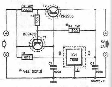
This power supply circuit is designed to provide a high current 5-volt output using a 7805 voltage regulator along with several standard electronic components. The transistor T1 functions as a current limiter. When the voltage across resistors R2 and...
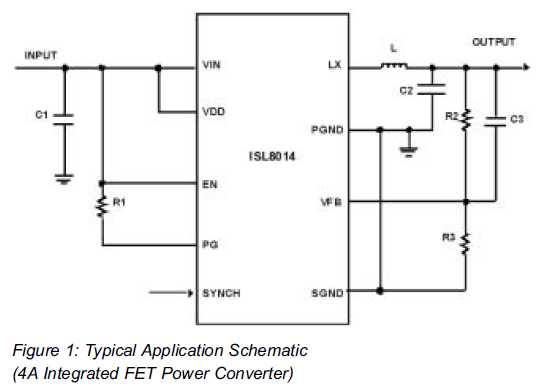
Utilizing Integrated Switching Regulators in Power Supply Design Engineers often find themselves pondering where to begin when designing power supplies. Key decisions must be made regarding... Integrated switching regulators are critical components in modern power supply design, offering efficient voltage...
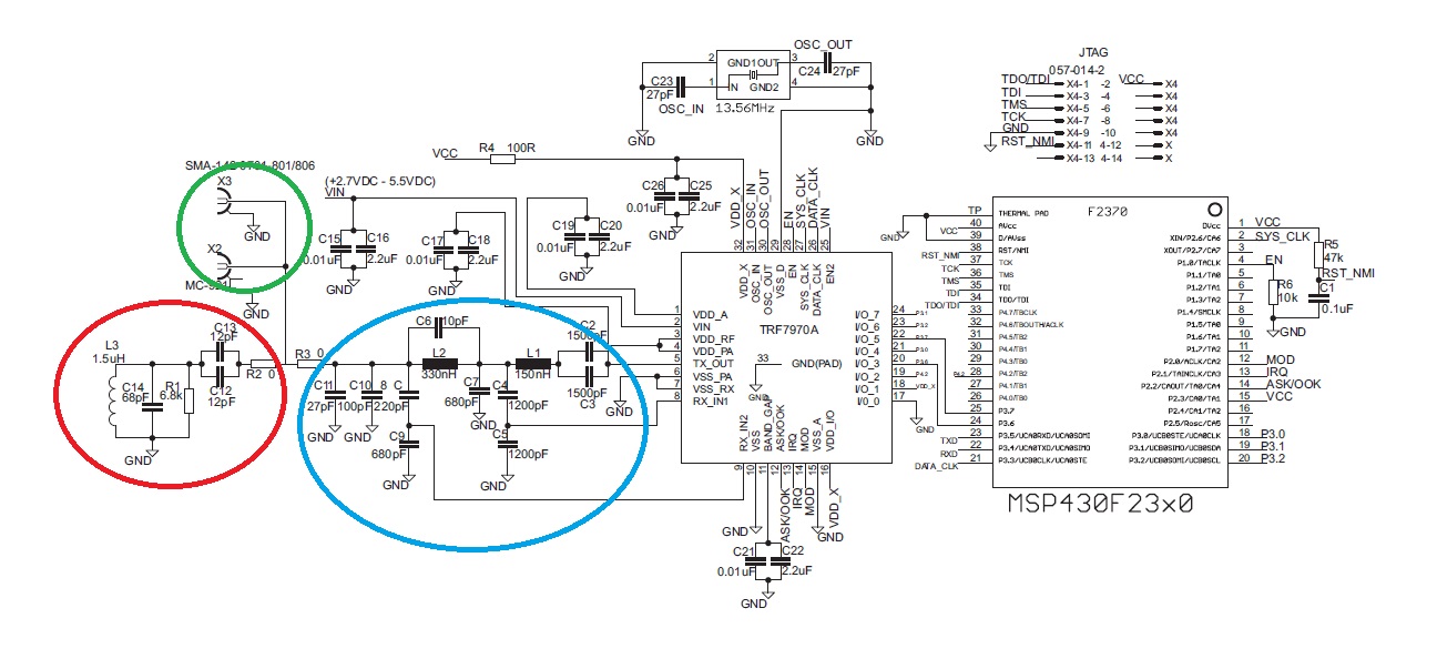
The "green area" is designated for the placement of the TRF7970A's antenna, which should be connected between two 0-ohm resistors. The antenna can be constructed step by step following the guidelines in the document "Antenna Matching for the TRF7960...
More: A comprehensive electronic schematic involves the representation of electrical components and their interconnections in a circuit. Each component is typically represented by standardized symbols, and the connections between them are depicted using lines. The schematic provides essential information...
This application note provides a concise overview of power amplifier theory and presents simulation results that offer insights into the operation of the power amplifier across all of MAXIM's LFRF transmitters and transceivers. Power amplifiers are critical components in communication...
A 100W RF power amplifier circuit is constructed using two BLY94 transistors. For additional RF amplifier options, refer to the list below. Components include active components. The 100W RF power amplifier circuit utilizing BLY94 transistors is designed to amplify radio...