
Power Amplifier Theory for High-Efficiency Low-Cost ISM-Band Transmitters

Power amplifiers are critical components in communication systems, responsible for boosting the power of radio frequency (RF) signals to ensure effective transmission over distances. The theory behind power amplifiers involves understanding their operating classes (Class A, B, AB, C, etc.), efficiency, linearity, and gain characteristics. Each class has distinct advantages and disadvantages, influencing their application in various systems.
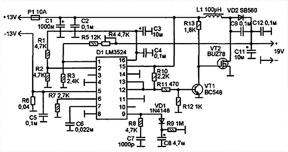
The simulation results included in this application note are essential for analyzing the performance metrics of power amplifiers used in MAXIM's LFRF transmitters and transceivers. These metrics typically encompass output power, efficiency, linearity, and distortion levels. By simulating different operational scenarios, engineers can predict how the power amplifier will behave under varying conditions, such as changes in load impedance or input signal levels.
In practical applications, the design of a power amplifier circuit must consider several factors, including thermal management, power supply requirements, and the integration of feedback mechanisms to enhance linearity and reduce distortion. The choice of transistors, biasing techniques, and matching networks also plays a significant role in the overall performance of the amplifier.
Furthermore, understanding the interaction between the power amplifier and other components in the transmitter or transceiver chain is crucial. This includes the effects of impedance matching, signal routing, and filtering, which can significantly impact the efficiency and effectiveness of the RF transmission.
In summary, the application note serves as a valuable resource for engineers and designers working with power amplifiers in RF communication systems, providing both theoretical knowledge and practical insights through simulation data. This information is vital for optimizing the design and performance of transmitters and transceivers in various applications.This application note includes a brief overview of power amplifier theory and it includes simulation results that provide insight into the operation of the power amplifier on all of MAXIM s LFRF transmitters and transceivers.. 🔗 External reference
Related Circuits
Laptops, commonly referred to as notebook computers, have gained significant popularity. Their portable design allows them to be easily transported in a bag, making them suitable for business trips and serving as convenient home entertainment centers due to their...
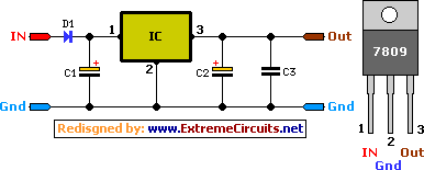
A simple 9 Volt, 2 amp power supply utilizing a single integrated circuit (IC) regulator. This circuit is straightforward, as the regulator handles the majority of the work. The component used is the 7809 voltage regulator. The circuit consists primarily...
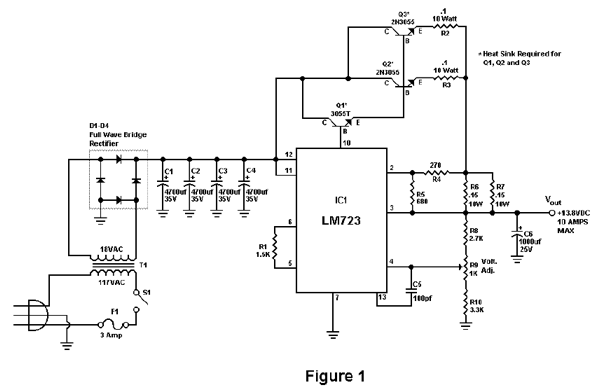
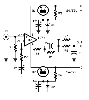
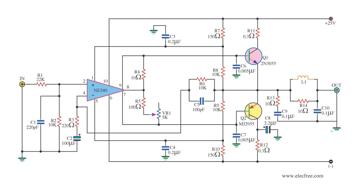
Activated this and inadvertently destroyed several 2N3055 transistors by shorting the emitters to ground. In all cases, the transistors opened up, and no damage to the emitter occurred in any transistor. The alternative circuit in Figure 2 will provide...
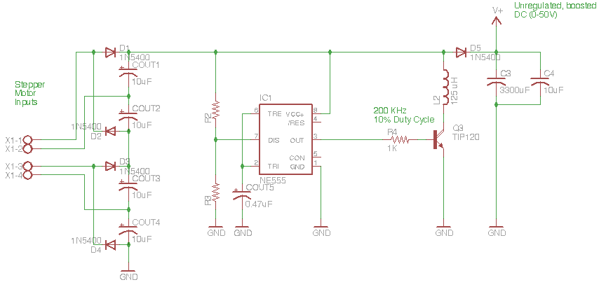
The circuit depicted in the schematic below represents an enhanced generator electronics system. It is an unregulated switcher designed to maximize sound output while ensuring prolonged CPU operation. This circuit efficiently transfers electrical energy from the generator, outperforming traditional...
Simple circuitry suitable for moving-magnet cartridges. Passive high-frequency equalization. This simple but efficient circuit devised for cheap moving-magnet cartridges can be used in connection with the audio power amplifiers shown in these webpages, featuring low noise, good RIAA frequency...
When the power supply reaches the circuit and the input signal is applied, the sound signal is processed through capacitor C1 and resistor R1 for signal coupling and noise reduction. The modified signal then reaches pin 3 (non-inverting) of...