
Adjustable output regulator

The circuit employs an operational amplifier (op-amp) to enhance the functionality of a voltage regulator. The op-amp can be configured in various ways, such as in a non-inverting or inverting configuration, to achieve the desired output voltage levels. By integrating the op-amp, the circuit can dynamically adjust the output voltage, allowing for a range of voltages that exceed the standard output of the regulator.
In this setup, the op-amp monitors the output voltage and compares it to a reference voltage. If the output voltage deviates from the desired level, the op-amp adjusts the control signal sent to the regulator, thereby fine-tuning the output. This feedback mechanism is crucial for maintaining stability and accuracy in the output voltage.
The design also specifies that the minimum output voltage from this arrangement is 2 volts higher than the voltage provided by the regulator alone. This characteristic ensures that the circuit can provide a higher voltage range, which may be necessary for specific applications requiring elevated voltage levels without sacrificing the regulation performance.
In practical applications, the choice of op-amp and its configuration will depend on factors such as bandwidth, slew rate, and power supply requirements. Proper selection and implementation of the op-amp will enhance the overall performance of the voltage regulation system, ensuring reliable operation under varying load conditions.The addition of an operational amplifier allows adjustment to higher or intermediate values while retaining regulation characteristics The minimum voltage obtainable with this arrangement is 2 volts greater than the regulator voltage.
Related Circuits
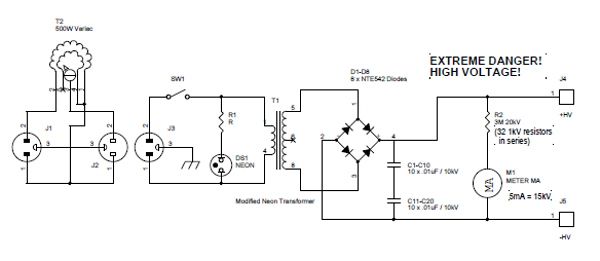
Transformers designed for powering large neon signs are cost-effective and highly reliable. Typically, the secondary winding is center-tapped, which restricts the full utilization of its peak-to-peak output in scenarios where one terminal must be grounded. In the power supply...
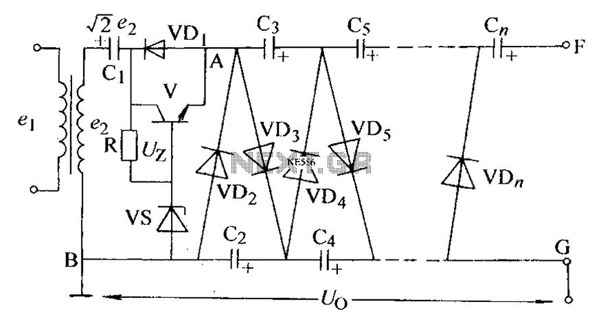
The circuit is an adjustable output voltage regulator type rectifier. It allows for obtaining peak voltage at odd multiples when the output voltage is taken from the circuit feedback (FB). Additionally, the lower point of the capacitor (CB) can...
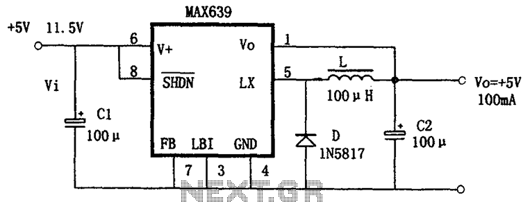
The circuit is based on the MAX639, which is a high-efficiency, step-down DC/DC converter. It operates with an input voltage range of 5.5V to 11.5V, providing a fixed output voltage of +5V or an adjustable voltage. The output current...
The Analog Devices ACP3610 is a voltage doubler that operates using a switched-capacitor converter based on the push-pull principle. The output switching frequency is approximately 550 kHz. The push-pull configuration involves two charge pumps that function in parallel but...
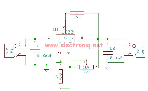
The following circuit illustrates the L200 Regulator Power Supply Circuit Diagram. Features include its use in power supply applications with specified voltage and current. The L200 voltage regulator is a versatile and adjustable linear regulator designed for various power supply...
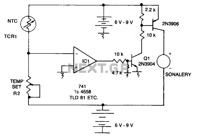
As the resistance (Rl) increases with a decrease in temperature, the output of integrated circuit IC1 becomes positive, activating transistor Q1. When Q1 conducts, it also triggers transistor Q2, which in turn activates the audible alarm. The threshold level...