
Adjustable Regulated Power Supply 0-15V

The adjustable regulated power supply circuit is designed for versatility and user-friendliness, making it suitable for various applications in electronics. The LM723 voltage regulator IC is a pivotal component in this design, allowing for an adjustable output voltage across a wide range, which is particularly useful for powering different electronic devices that require specific voltage levels. The integration of the 78L05 voltage regulator enhances the circuit's capability to provide stable output even under varying load conditions.
The TDA2030 audio amplifier IC serves a dual purpose in this circuit; not only does it assist in voltage regulation, but it also provides amplification, ensuring that the output remains stable under load. This feature is critical in applications where consistent power delivery is essential.
Furthermore, the inclusion of the L161 micro power quad comparator allows for additional functionality, enabling the circuit to operate efficiently with minimal power consumption. This aspect is particularly beneficial in battery-operated devices or applications where power efficiency is a priority.
The inverter circuit adds another layer of versatility, allowing for the conversion of lower DC voltages to higher levels, which can be advantageous in powering devices that require different voltage inputs. The overall design is modular, with clearly defined components that can be easily sourced, making it an excellent choice for both hobbyists and professionals looking to implement an adjustable power supply solution.Adjustable Regulated Power Supply 0-15V 1A. Adjustable Regulated Power Supply 0-15V 1A. The output voltage is stabilized and regulated in the range of 0V to 15 V, supplied with a maximum current of 1A. The schematic diagram come from circuit: Adjustable Regulated Power Supply 0-15V / 1A power supply. Go to that page to read the explanation about above power supply related circuit diagram. This is the schematic diagram of adjustable power supply which the voltage output can be vary from 0V up to 15V with fixed current output maximum of 1A. The circuit is very simple and easy to build, finding the components. This Adjustable regulated power supply circuit uses voltage regulator LM723 IC which are already well known.
IC LM 723 is designed to provide a voltage of 2-37 volt supply voltage with 150mA current, and this current is small indeed, but. In this scheme, adjustable voltage regulator IC 78L05 is used in conjunction with the integrated audio amplifier TDA2030.
Because of this, the stabilizer was very simple. The output voltage is regulated to 20 V with maximum current of 3. The Regulated DC to DC Converter circuit based on Micro Power Quad Comparator L161 IC that have ultra low power consumption. This inverter circuit convert 5 Volt DC to 12 Volt DC 5 mA. This low power dc to dc. This is a 40V Regulated Power Supply, built using IC LM317 as regulator and TIP42A as electric current amplifier.
Component part: Regulated Power Supply R1 = 3R9 1 or 2W R2 = 22R R3 = 6K8 R4 = 220R R5. We aim to transmit more information by carrying articles. Please send us an E-mail to wanghuali@hqew. net within 15 days if we are involved in the problems of article content, copyright or other problems. We will delete it soon. 🔗 External reference
Related Circuits
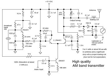
In many discussions of LPAM transmitter design, references to "the Wenzel circuit" or "the Wenzel transmitter" are common. These terms refer to a clever transmitter design that became popular in the mid-1990s and early 2000s for those interested in...
The amplifier is based on the commonly used class-AB complementary power amplifier with compound pair output transistors. The system uses a TL074 quad opamp to drive the output transistors. As can be seen from figure 1, A2 is used to...
This circuit generates three source-regulated voltages using a minimal number of electronic components. The output DC voltages are +12V, +5V, and -5V. Diodes D2 and D3 perform full-wave rectification while charging capacitor C2 during each half of the alternating...
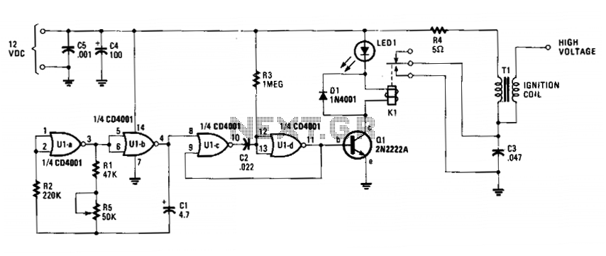
The circuit is fundamentally an auto ignition coil paired with a set of points that perform a similar function. It employs a pulsing circuit constructed from a single CMOS NOR integrated circuit (U1) to open and close relay contacts,...
This circuit can be adapted for other regulated and unregulated voltages by using different regulators and batteries. For a 15 Volt regulated supply use two 12 Volt batteries in series and a 7815 regulator. There is a lot of...
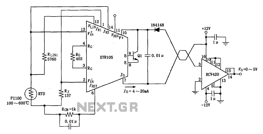
The circuit utilizes a Pt100 type resistance temperature detector (RTD). It operates within a temperature range of 100 to 600 °C, where the XTR105 outputs a current of 4 to 20 mA, and the RCV420 provides an output voltage...