
Basic UPS Power Supply

The described circuit is a versatile power supply that can accommodate various voltage requirements through the selection of appropriate voltage regulators and battery configurations. The primary component for achieving a regulated 15 Volt output is the 7815 voltage regulator, which is designed to provide a stable output voltage of 15 Volts with a maximum output current typically around 1.5 Amperes.
To achieve the required input voltage for the 7815 regulator, two 12 Volt lead-acid batteries are connected in series. This series configuration results in a total input voltage of 24 Volts, which is sufficient for the 7815 to function correctly, as it requires a minimum input voltage of approximately 17 Volts to maintain regulation.
The circuit design should include additional components for optimal performance and safety. A pair of decoupling capacitors (typically 0.33 µF and 0.1 µF) can be placed at the input and output terminals of the 7815 regulator to filter out high-frequency noise and ensure stability. Additionally, a larger electrolytic capacitor (e.g., 100 µF) at the output may help maintain voltage stability during transient load changes.
For applications requiring different output voltages, alternative voltage regulators can be utilized in conjunction with various battery configurations. For instance, using a 7809 regulator in a similar setup with a single 12 Volt battery would yield a regulated output of 9 Volts. The flexibility of the circuit allows for customization based on specific voltage and current requirements, making it suitable for a wide range of electronic applications.
It is essential to consider thermal management, as voltage regulators can dissipate heat during operation. A heat sink may be necessary for the 7815 regulator to prevent overheating, especially under higher load conditions. Proper circuit layout and component selection will ensure reliable operation across different voltage configurations.This circuit can be adapted for other regulated and unregulated voltages by using different regulators and batteries. For a 15 Volt regulated supply use two 12 Volt batteries in series and a 7815 regulator. There is a lot of flexibility in this circuit. 🔗 External reference
Related Circuits
The MAX5953A offers a straightforward, cost-effective, and comprehensive non-isolated power integrated circuit (IC) solution for Powered Devices (PD) in Power-over-Ethernet (PoE) systems. The MAX5953A is designed to facilitate the implementation of Power-over-Ethernet applications by providing an efficient means of...
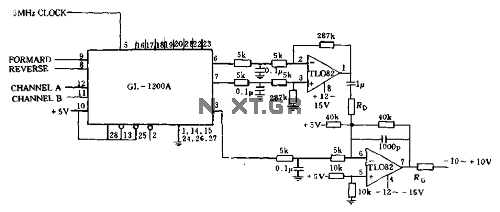
The error processing segment is converted into a pulse width modulated (PWM) signal output from 3 feet (MC signal). Additionally, the differential position error is calculated, which represents the small velocity, from 6 to 7 feet, selected as a...

Three power levels are provided by the two logic inputs of this enhanced circuit. R5, D4, D5, and O2 create a power supply for the logic integrated circuit. These components can be excluded if an alternative low voltage source...
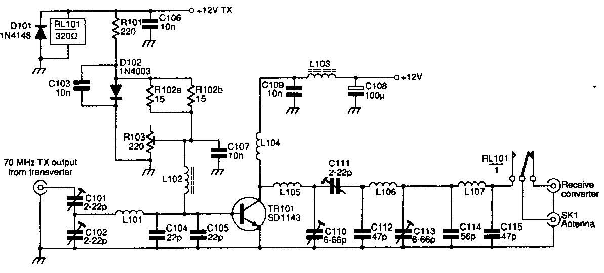
This 70 MHz RF power amplifier circuit utilizes the SD1143 transistor, which offers a gain of approximately 14 dB in this configuration. The design leverages the characteristics of a 175 MHz device. The RF power amplifier circuit designed around the...
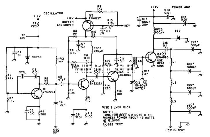
Suitable for amateur use, this 1.5-W transmitter operates on a 12-V supply. Q1 functions as an oscillator utilizing a surplus FT243 crystal. Q2 serves as a buffer driver and is activated through the keying transistor Q5. Q3 acts as...
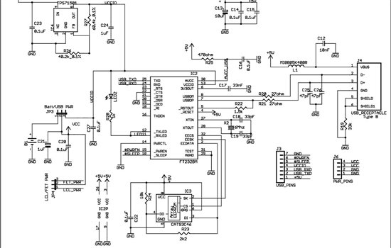
As found in SLAA458, the revised pulse oximeter application, an image of the USB schematic is attached, which is used to output collected data. There are a few questions regarding this schematic: 1) What do J3 and J6 correspond...