
Adjustable Sine/Square Wave Oscillator

The schematic features a configuration that allows for the generation of both sine and square wave outputs, making it suitable for a variety of applications, including audio signal generation, testing, and waveform analysis. The circuit typically employs operational amplifiers (op-amps) in conjunction with passive components such as resistors and capacitors to establish the desired frequency response and waveform shape.
In the sine wave generation section, a feedback loop is created using op-amps configured in an integrator and a Schmitt trigger. The integrator converts a square wave input into a sine wave output by integrating the square wave signal, while the Schmitt trigger ensures that the output maintains a clean, stable waveform by providing hysteresis. The frequency of oscillation can be adjusted by varying the values of the resistors and capacitors in the feedback loop, allowing for fine-tuning of the output frequency.
For the square wave output, the circuit can utilize the same op-amps, with the output from the Schmitt trigger providing a square wave signal directly. This dual functionality of generating both sine and square waves from a single circuit design enhances the utility of the oscillator.
The circuit is powered by a suitable DC power supply, ensuring that the op-amps operate within their specified voltage range. Proper bypassing capacitors should be included to filter out any power supply noise that may affect the oscillator's performance. Additionally, output stages may be incorporated to buffer the signals and provide the necessary drive capability for external loads.
Overall, this adjustable sine and square wave oscillator schematic presents a flexible solution for generating various waveforms across a wide frequency range, making it an invaluable tool for electronic experimentation and development.The following diagram is the schematic of simple easily tuned / adjustable sine and square wave oscillator. This circuit provides sine and square wave at frequency of below 20Hz up to above 20KHz. The benefit of this circuit diagram is that.. 🔗 External reference
Related Circuits
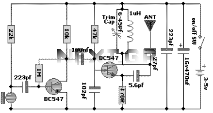
The following schematic diagram shows the design of a 100 MHz Radio Frequency RF Oscillator Circuit. The electrets microphone picks up and amplifies sound then fed it into the audio amplifier stage built around the first transistor. The output...
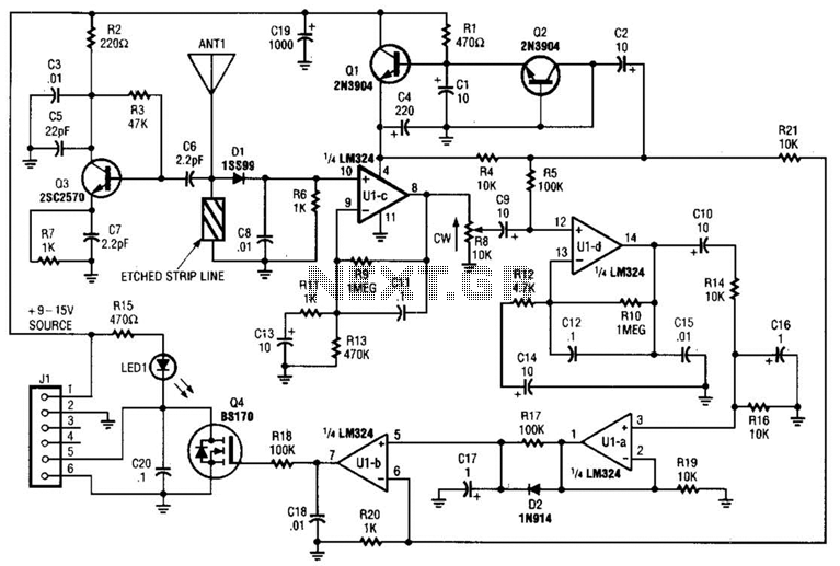
Operating at approximately 1.1 GHz, the detector senses disturbances in the electromagnetic field surrounding the antenna. The Doppler signal generated by detector D1 is amplified and used to control a power MOSFET switch. The antenna consists of a short...
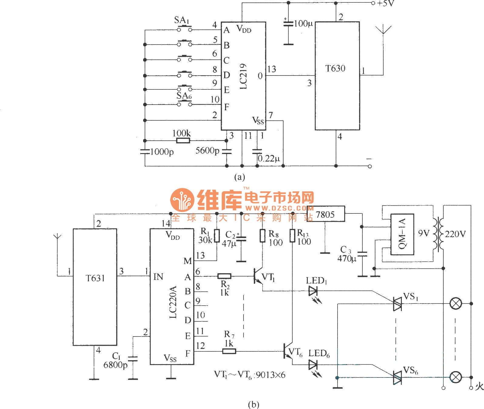
The circuit utilizes the long-wave wireless transceiver T630/T631 to manage a 6-channel load. It is characterized by low power consumption, high resistance to interference, and a simple structure. The circuit design incorporates the T630/T631 transceiver, which operates in the long-wave...
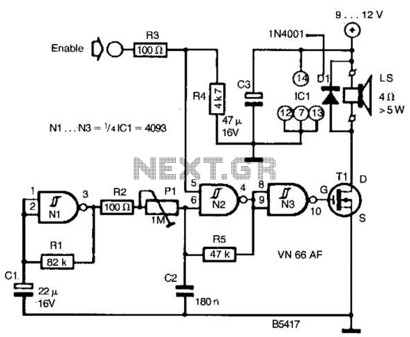
A CD4093 chip and several components form a siren oscillator that drives power MOSFET Tl. A speaker is directly powered by this device. The siren is activated by a logic high signal applied to the ENABLE input. The circuit comprises...
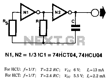
When frequency stability is not of primary importance, a simple yet reliable digital clock oscillator can be constructed using relatively few components. High-speed CMOS (HCU/HCf) inverters or gates with an inverter function are particularly suitable for creating such oscillators...
The oscillator employs a fundamental quartz crystal, capable of achieving an oscillation frequency of up to 10 MHz. The oscillator circuit is calibrated to the resonant frequency of the crystal. A capacitor, designated as C, with a value of...