
Microwave Motion Detector Circuit

The circuit operates in the microwave frequency range, specifically around 1.1 GHz, indicating it is likely designed for applications such as motion detection or radar systems. The antenna, being a short wire, is utilized for its simplicity and effectiveness in capturing high-frequency signals. Its length, being between 2 to 3 units, suggests that it is designed for optimal performance at the specified frequency, likely acting as a monopole antenna.
The detector, referred to as D1, plays a crucial role in sensing variations in the electromagnetic field. It converts the incoming electromagnetic waves into an electrical signal, which is then processed to identify any disturbances. The Doppler effect is utilized here, where the frequency shift of the reflected signals indicates movement within the detection range. This is particularly useful in security systems, automotive applications, or any scenario requiring motion detection.
The amplified Doppler signal is then fed into a power MOSFET switch. This component is selected for its high efficiency and fast switching capabilities, making it suitable for controlling larger loads or triggering other components in the circuit based on the detected signal. The MOSFET's gate can be driven by the amplified signal, allowing it to switch on or off rapidly in response to changes in the detected field, thus enabling real-time monitoring and response.
Overall, this circuit design effectively integrates an antenna, a detector, and a power switch to create a responsive system capable of detecting motion or field disturbances, making it applicable in various electronic and communication systems. Operating at around 1.1 GHz, the detector senses field disturbance in the neighborhood of the antenna. The Doppler signal from detector D1 is amplified and drives a power MOSFET switch. The antenna is a short (2 to 3) length of wire.
Related Circuits
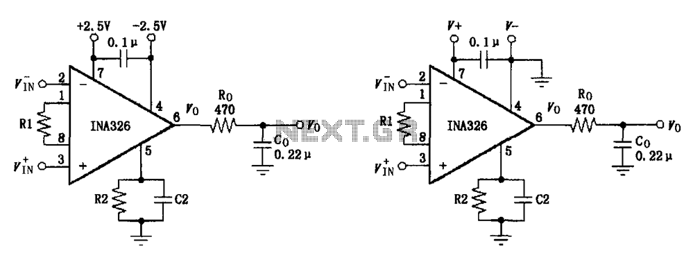
The basic connection circuit for the INA326/327 includes signals and power. A 0.1 µF capacitor is selected for power supply filtering and should be placed as close to the chip's supply pin as possible. Ro and Co serve as...
The Park Aid system utilizes three LEDs to indicate the distance of a bumper barrier through infrared operation, designed for indoor use. The circuit diagram includes the following components: R1 (10K 1/4W resistor), R2, R5, R6, R9 (1K 1/4W...
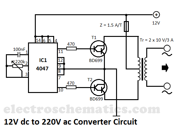
This DIY 12V to 220V voltage converter is built with the CMOS 4047, which serves as the main component of this compact voltage converter that transforms 12V DC into 220V AC. The 4047 is configured as an astable multivibrator,...
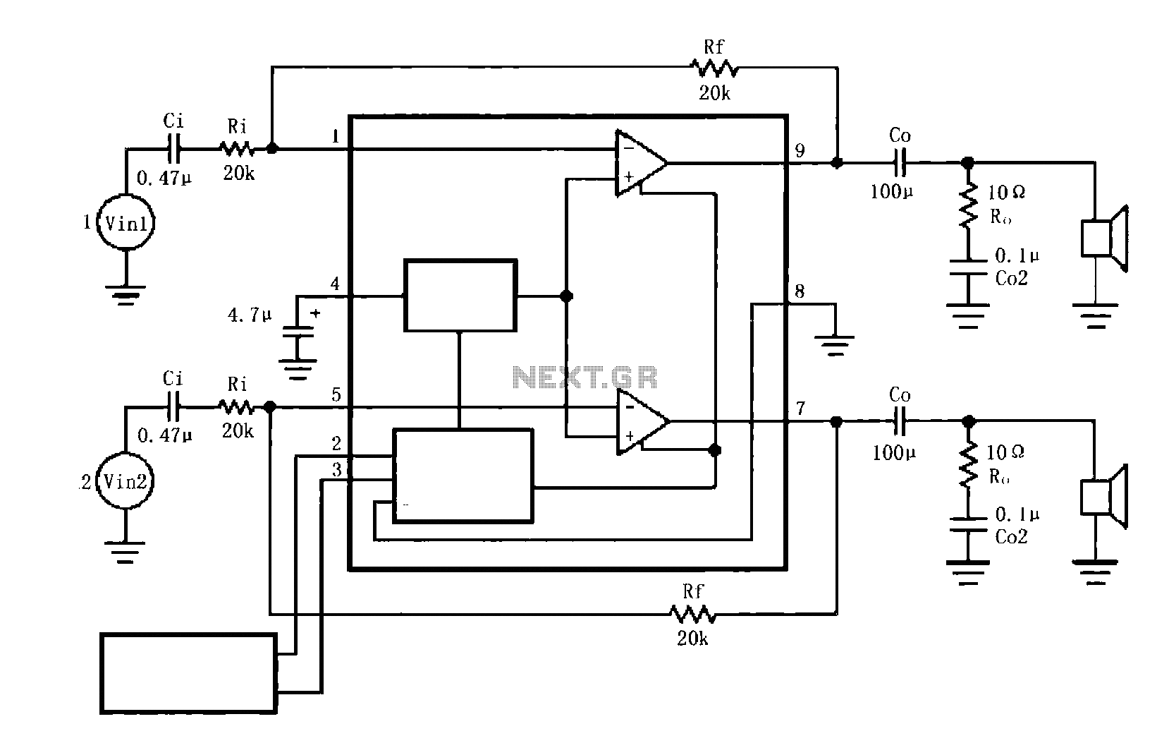
The circuit illustrated is a typical configuration for the LM4916 two-channel amplifier. The left and right channel audio signals are fed into the LM4916, which amplifies them internally. The output is then delivered through a coupling capacitor (Co) to...
120V galvanic acupuncture salmon RI. The system features a wind-down rectification and a limit irrigation mechanism to achieve an amplitude of 24V. It includes isolation diodes and a steady stream over the circuit. The design ensures that a voltage...

A tremolo circuit is a type of sound effect commonly utilized in guitar effect pedals. This effect is achieved by modulating the amplitude of an audio signal. The shape of the modulating signal can vary and may include square...