
Adjustable thermostat controller circuit diagram created REF01E

The adjustable thermostat controller circuit is designed to maintain specific temperature levels in various applications. The TMP17 temperature sensor plays a crucial role by providing accurate temperature readings. The REF01E serves as a precision voltage reference, ensuring that the circuit operates with a consistent 10V supply, which is essential for reliable performance.
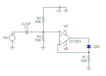
Resistor R1 is strategically placed to convert the temperature reading from the TMP17 into a proportional voltage signal. This voltage signal is then fed into the AD790 voltage comparator, which functions as a threshold detector. The comparator compares the voltage corresponding to the measured temperature (t) against a predetermined set temperature (t0).
When the measured temperature reaches the set point, the output of the AD790 transitions to a low state, signaling that the desired temperature has been achieved. This output can be used to control heating elements, such as those found in soldering irons, by turning them off or on as needed to maintain the set temperature.
In summary, this adjustable thermostat controller circuit combines a temperature sensor, a precision voltage reference, and a voltage comparator to create an efficient and reliable temperature control system suitable for various applications, particularly in soldering and other temperature-sensitive processes.Adjustable thermostat controller circuit is very long use in everyday life, such as constant temperature soldering iron, as shown in FIG. TMP17 by the REF01E to provide a high degree of stability 10V supply voltage across the resistor R1 can be obtained with the measured voltage signal proportional to the temperature t. AD790 voltage comparator. Order t, t0 represent the measured value and the set value of the temperature, when t t0 when the thermostat output is low, t
Related Circuits
Common Light Emitting Diodes (LEDs) require a direct current (DC) forward bias of 10 to 20 mA for optimal performance. The maximum allowable DC current typically ranges from 30 to 50 mA. The emitted light color, or wavelength, from...
Using a K-12 tube amplifier with a NAD C542 CD player eliminates the necessity for a buffer or line-level preamplifier. The K-12 amplifier is characterized by its polite and sweet sound, embodying the warmth typical of its "hot bottle"...
This device is a combination digital clock timer and solar panel charge controller designed to maintain a deep cycle battery from a solar panel. The timer output controls a 12-volt load for a 32-minute interval each day. The start...
Connect the serial cable to the serial port. If using a USB to TTL, RS232, or serial converter, plug it into the USB port. Next, short the Tx pin to the Rx pin or the TxD pin to the...

This circuit design generates a stable 1 kHz sine wave using an inverted Wien bridge configuration with components C1-R3 and C2-R4. It offers a variable output, low distortion, and low output impedance to ensure good overload capability. The circuit...
Build a large dancing robot. This was intended to be a walking robot, but it ended up moving in a more rhythmic manner. A video is available in the last step. The project involves the construction of a large dancing...