
digital clock circuit diagram

The digital clock timer and solar panel charge controller circuit integrates several key functionalities. The timer's ability to control a 12-volt load for a predetermined duration is critical for applications where energy management is essential, such as in remote solar-powered systems. The use of a 4040 binary counter allows for flexible timing options, providing versatility in energy consumption.
The clock circuitry utilizes a standard crystal oscillator, ensuring accurate timekeeping, while the binary counting approach simplifies the design and minimizes component count. The cascading of counters and latches allows for efficient time representation and display management. The use of multiplexers to toggle between display modes enhances user interaction, allowing for intuitive adjustments.
The voltage regulation aspect of the circuit is vital for maintaining battery health, preventing overcharging, and ensuring that the connected load receives stable voltage. The inclusion of a visual battery condition indicator improves system reliability by providing real-time feedback on battery status, thus facilitating proactive maintenance.
Overall, this combination device not only serves as a reliable timekeeping solution but also enhances the efficiency of solar energy utilization, making it suitable for various applications in renewable energy systems.This is a combination digital clock timer and solar panel charge controller used to maintain a deep cycle battery from a solar panel. The timer output is used to control a 12 volt load for a 32 minute time interval each day. Start time is set using 9 dip switches and ends 32 minutes later. The 32 minute duration is set by selecting the 5th bit of a 4040 binary counter (pin 2). The timer also has a manual toggle switch so the load can be manually switched on or off and automatically shuts off after 32 minutes. The time duration can be longer or shorter (8, 16, 32, 64, 128, 256 minutes etc. ) by selecting the appropriate bit of the counter. The timer circuit is shown in the lower schematic just above the regulator. The basic clock circuit (top schematic below) is similar to the binary clock (on another page) and uses 7 ICs to produce the 20 digital bits for 12 hour time, plus AM and PM.
A standard watch crystal oscillator (32, 768) is used as the time base and is divided down to 1/2 half second by the 4020 binary counter. One half of a 4013 data latch is used to divide the 1/2 second signal by 2 and produce a one second pulse that drives the seconds counter (74HC390 colored purple).
The minutes are advanced by decoding 60 seconds (40 + 20) and then resetting the seconds counter to 0 and at the same time advancing the minutes counter. The same procedure is used to advance the hours. The second half of the 4013 latch is used to indicate AM or PM and is toggled by decoding 13 hours and resetting the hours to 0 and then advancing the hours to "one".
The clock display circuit is shown in the second drawing below and uses 6 more ICs to decode the binary data and drive four seven segment LED displays. The 10s of hours digit is driven with a single 3904 transistor. Two multiplexer circuits (4053) are used to manually select either minutes or seconds for the right two display digits.
The two switches shown between the 4053s and below the left 4053 are both part of one DPDT switch which selects either seconds or minutes for the 1X and 10X digits. This switch is shown in the seconds position and the hours digits are blanked with a low signal on pin 4 of the 4511.
The display can also be toggled on and off (totally blank) using a set/reset latch made from a couple 74HC00 NAND gates. A momentary DPDT switch is used to control the latch and toggle the display on or off. The second pole of this switch is used on the upper drawing (connected to the run/stop switch) to set the hours and minutes.
Thus this same switch performs both functions of blanking the display and setting the time. The run/stop switch is shown in the normal running mode and supplies a low signal to a NAND gate which prevents accidental setting the time while the clock is running. The run/stop switch also turns on the display (through the diode D2) when in the stop position. The procedure for setting the clock would be to set the (run/stop) switch the stop position and the (seconds/minutes) switch to the minutes position.
Then toggle the momentary switch to set minutes and hours of the current time plus one minute. The clock can then be started with the run/stop switch at precisely the right time (+/- 0. 5 seconds). The voltage regulator in the lower drawing maintains the battery at 13. 6 volts and also supplies the clock and timer circuits with 4. 3 volts. The charge LED indicator only comes on when the regulator is supplying max charge to the battery. When the battery voltage reaches 13. 6 the regulator reduces the current to whatever is necessary to maintain the voltage and the charge indicator will turn off. The unit I built also included a battery condition indicator (voltmeter using 4 LEDs) to indicate the battery condition so that a failure of the regulator would be indicated by the charge indicator LED turned off and less than 4 LEDs lit on the voltmeter.
🔗 External reference
Related Circuits
This regulated power supply can be adjusted from 3 to 25 volts and is current limited to 2 amps as shown, but may be increased to 3 amps or more by selecting a smaller current sense resistor (0.3 ohm)....
The circuit presented is experimental and should provide some fun to build and play about with. It has been built and tested and works very well indeed. Please note that it is a low current Class-A opamp and is...

The schematic closely resembles the one found in the CPLD Development Board Tutorial, as it is essentially the same board with a minor addition. The new components are located in the lower right corner, including eight DIP switches, a...
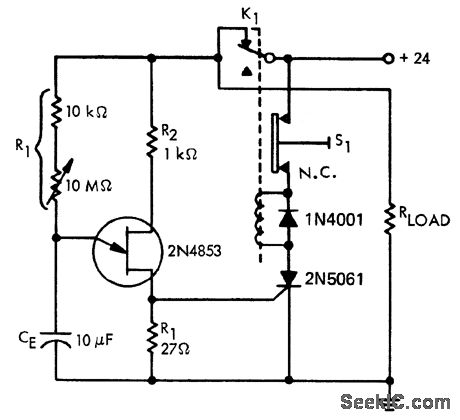
A time delay circuit utilizing a Unijunction Transistor (UJT). The maximum time delay is adjustable via a 10 MΩ potentiometer, allowing the time delay to be configured from less than one second to approximately 2.5 minutes, as referenced by...
A schematic arrangement for a two-quadrant controller is shown in the figure below. This figure illustrates the outer speed control loop and the inner current control loop. The tachogenerator derives the speed feedback signal; alternatively, an approximation of the...
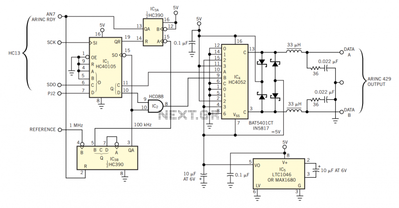
The physical transmission medium for the 429 standard is 78Ω shielded, twisted-pair cable that uses a complementary, differential bipolar RZ (return-to-zero) waveform. The voltages are the net differentials that the biphase drive develops: For example, the differential is 10V...