
Adjustable Timer

The described circuit utilizes two LED indicators to convey the operational status of a timer-based system. The reset switch, designated as SI, initiates the timer's state, which is maintained until the start switch, labeled S2, is engaged. This functionality allows for a clear visual representation of the timer's readiness and operational status.
LED1 serves as the "ready" indicator, illuminating when the circuit is primed for operation. Conversely, LED2 functions as a time indicator, signaling the active timing phase. The choice of color coding for these LEDs enhances user comprehension, with red typically associated with standby or readiness and green indicating that the timer is actively counting.
The circuit design should ensure that both LEDs are connected in parallel to the output of the respective switches, with appropriate current-limiting resistors included to prevent LED damage. The reset switch should be configured to momentarily ground the timer circuit, allowing it to reset to its initial state. The start switch, when pressed, should initiate the timing sequence while simultaneously illuminating LED2 to indicate that the timer is in operation.
For optimal performance, the circuit may include additional features such as debouncing for the switches to avoid false triggering, as well as a microcontroller or timer IC to manage timing functions. This would allow for more complex timing operations and enhanced functionality, such as adjustable timing intervals or additional status indicators. Overall, the design should prioritize clarity and user-friendliness, ensuring that the LED indicators provide immediate feedback regarding the status of the timer circuit. LEDs indicate at a glance what the status of the circuit is at any given moment. Once the reset switch, SI, makes contact, the timer remains in that state until the start switch, S2, is pressed. When either switch is activated, LED1 (ready) and the time indicator, LED2, keep track of the situation. Although not necessary, the two LEDs should be of different colors (for example, red for "ready" and green for "time").
Related Circuits
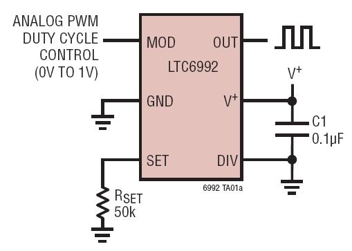
The LTC6990 is a precision silicon oscillator with a programmable frequency range of 488Hz to 2MHz. It can function as either a fixed-frequency oscillator or a voltage-controlled oscillator (VCO). The LTC6990 belongs to the TimerBlox family of versatile silicon...
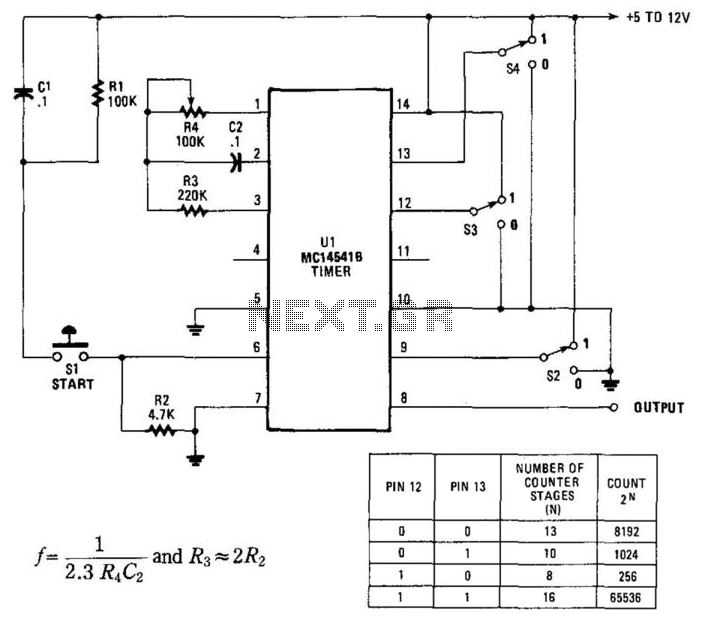
By utilizing an RC oscillator and a programmable divider, this counter can operate for extended periods. The interval oscillator functions at a frequency determined by specific component values: for instance, with R1 = 390 kΩ and C2 = 10...
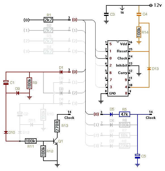
This circuit utilizes a CMOS 4017 decade counter, which begins counting from zero and increments by one each time pin 14 is activated. Upon reaching a count of nine, it resets to zero and starts the counting process again....
A simple astable timer is constructed using a 555 timer IC. The mark (on) and space (off) durations can be set independently. The timing circuit comprises resistors Ra, Rb, and capacitor Ct. The capacitor Ct charges through resistor Ra,...
Considering the rapid advancements in the electronics industry, the 555 timer could be regarded as a constant in an ever-evolving landscape. What exactly is the 555 timer? How does it function? In what ways can it be utilized? And...
This is a sequence timer diagram composed of an NE555 timer. The timer can be set to any duration when the power is connected, allowing it to control an external system. In the circuit, K1-K3 are relays used to...