
asymmetric timer

The astable multivibrator configuration using the 555 timer operates continuously, switching between its high and low states to create a square wave output. The timing cycle consists of two intervals: the high state duration (T(on)) and the low state duration (T(off)). The output frequency (f) of the oscillator can be calculated using the formula:
\[ f = \frac{1.44}{(Ra + 2Rb) \cdot Ct} \]
where Ra and Rb are the resistances in ohms, and Ct is the capacitance in farads. The high state duration (T(on)) can be determined by:
\[ T(on) = (Ra + Rb) \cdot Ct \]
and the low state duration (T(off)) is given by:
\[ T(off) = Rb \cdot Ct \]
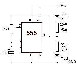
In this configuration, when the output is high, capacitor Ct charges through resistor Ra and the diode, allowing for a faster charge time due to the diode's forward conduction. Once the voltage across Ct reaches approximately two-thirds of the supply voltage (Vcc), the 555 timer switches states, and the capacitor begins to discharge through resistor Rb into pin 7. The discharge continues until the voltage drops below one-third of Vcc, at which point the cycle repeats.
To ensure accurate timing, it is crucial to select appropriate values for resistors Ra and Rb, as well as the capacitor Ct. The choice of components will influence the frequency and duty cycle of the output waveform. Additionally, external factors such as temperature and component tolerances can affect the timing accuracy, particularly for T(on), which is approximated due to the diode's characteristics. In practical applications, this astable timer circuit can be utilized in various timing, pulse generation, and oscillation applications, making it a versatile component in electronic design.A simple astable timer made with the 555, the mark (on) and space (off) values may be setindependently. The timing chain consists of resistors Ra, Rb and capacitor Ct. The capacitor, Ct charges via Ra which is in series with the 1N4148 diode. The discharge path is via Rb intointo pin 7 of the IC. Both halves of the timing period can now be set inde pendently. Please note that the formula for T(on) ignores the series resistance and forward voltageof the 1N4148 and is therefore approximate, but T(off) is not affected by D1 and is thereforeprecise. 🔗 External reference
Related Circuits
This circuit turns off an amplifier or any other device when a low-level audio signal fed to its input is absent for at least 15 minutes. Pressing P1 switches the device on, supplying power to any appliance connected to...
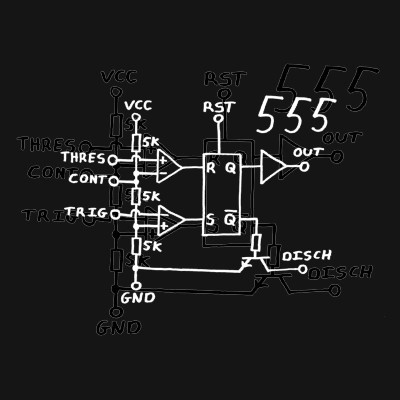
Classic 555 timer chip schematic circuit t-shirt by EEVblog picture on VisualizeUs - bookmark pictures and videos that inspire you. Social bookmarking of pictures and videos. Find your pictures and videos. The 555 timer IC is a versatile and widely...
To achieve a lower parts count than the two-transistor multivibrators, two LEDs can be alternately flashed using a 555 integrated circuit configured as illustrated in Schematic 2. A combination of a 2.2kΩ and a 47kΩ resistor is used to...
The CMOS 4060 integrated circuit (IC) features two built-in inverters located at pins 9, 10, and 11, which must be interconnected to create an oscillator. The output of this oscillator is available at Pin 9, which continuously alternates between...

The following circuit illustrates a Bedside Lamp Timer Circuit Diagram. This circuit is based on the CD4060 integrated circuit. Features: An LED illuminates for approximately 25 seconds. The Bedside Lamp Timer Circuit utilizes the CD4060 IC, which is a versatile...
This LED flasher circuit utilizes a 555 timer integrated circuit (IC). The circuit diagram is straightforward and requires only a few external components. When operational, the red LEDs will flash sequentially at a predetermined frequency, similar to the indicators...