
ADSL line filter

L1, L2 = 6.8mH, inductor
L3, L4 = 10mH, inductor
C1 = 0.022uF, 250-600V
C2 = 0.015uF, 250-600V
The described circuit is a low-pass filter designed specifically for telephone line applications, utilizing inductors and capacitors to attenuate high-frequency signals while allowing lower frequencies to pass through. The configuration includes two inductors (L1 and L2) with a value of 6.8 mH, and two additional inductors (L3 and L4) rated at 10 mH. This arrangement is crucial for filtering out unwanted noise and interference that may be present on the telephone line.
The filter employs two capacitors, C1 and C2, to complement the inductors. C1 is rated at 0.022 µF with a voltage rating between 250V and 600V, while C2 has a capacitance of 0.015 µF, also with a voltage rating in the same range. The choice of capacitors is significant; higher voltage ratings are preferred for durability and performance, and the 400V types are readily available in the market, making them a practical choice for this application.
In the context of telephone lines, the 'Tip' and 'Ring' conductors are the two wires used to carry the signal, which can experience voltages up to 90VAC. The inclusion of inductors L2 and L4 is essential for managing these voltages effectively, providing necessary isolation and protection for the connected devices.
The performance of this filter has been validated in practical applications, such as those experienced in early BBS (Bulletin Board System) setups, indicating its reliability and effectiveness in real-world scenarios. For further technical details and design considerations, references such as the ARRL Handbook may offer additional insights into similar filtering techniques and implementations.The above diagram is a standard low-pass telephone line filter (L1,C1,L3,C2). L2 and L4 are needed since we're dealing with the 'Tip' and 'Ring' of a phone line which may carry up to 90VAC. I used a similar circuit on 3 phone-lines back in the early 80's when I was running Scottsdale BBS and the filters performed fine.
Additional info can be found in the ARRL Handbook, etc. For the two capacitors, the higher the voltage the better, but the 400V types are the easiest to obtain. L1,L2 = 6.8mH, inductor L3,L4 = 10mH, inductor C1 = 0.022uF, 250-600V C2 = 0.015uF, 250-600V 🔗 External reference
Related Circuits
The project involves the creation of a line-follower robot. This microcontroller-based robot is designed to follow a black line on the ground. The line-follower robot utilizes a microcontroller as its central processing unit, which interprets input signals from various sensors...
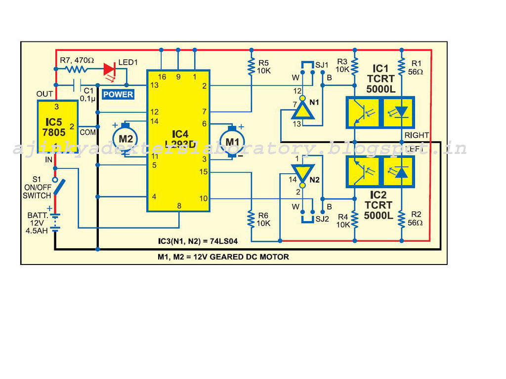
Carefully examine the following circuit diagram and attempt to construct the circuit on a breadboard first. If it functions correctly, proceed to create its PCB version. The circuit diagram serves as a blueprint for constructing an electronic circuit on a...
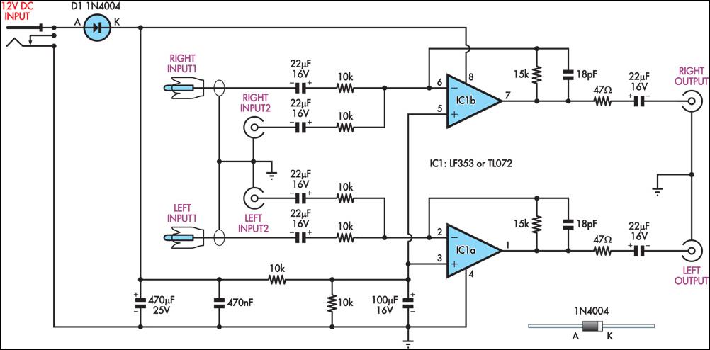
This circuit combines two separate line-level stereo (L & R) signals into one stereo (L & R) output, eliminating the need to switch between two pairs of input signals. It is utilized in a scenario where the stereo audio...
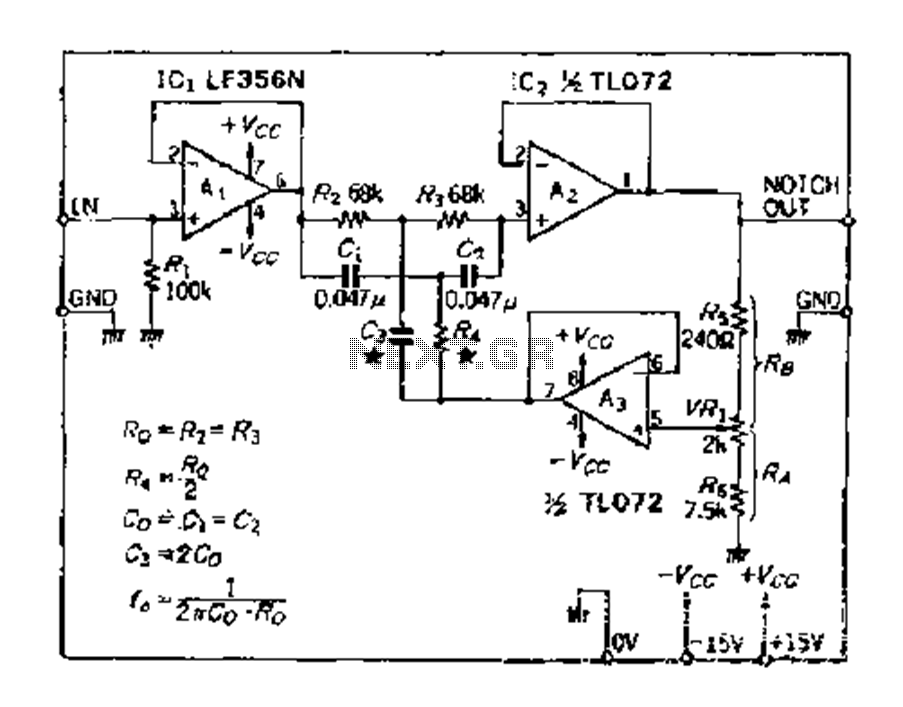
The double R circuit consists of three resistors and three capacitors, exhibiting substantially symmetrical double passive attenuation characteristics of the filter element with a frequency response range of 0 to 0.2. The parameters are determined as follows: Rz, R3,...
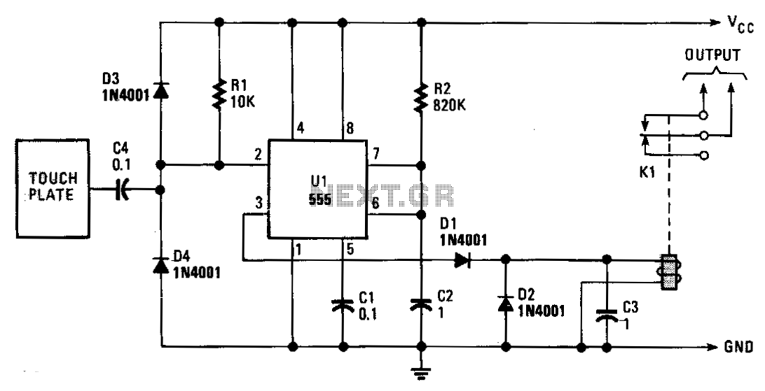
The monostable period is set for approximately 1 second, which is typical for this application. The induced line hum is transmitted through capacitor C2, resulting in a continuous stream of trigger pulses. The output remains low for about 10...
In the form it appears the theoretical circuit of filter. In first glance we see three different circuits that are mainly manufactured round two operational amplifiers. This circuits constitute mixed, amplifier with variable aid and a variable filter. The...