
The Q value of the variable notch filter

The double R circuit is a sophisticated filter design primarily utilized for signal processing applications. It comprises three resistors and three capacitors arranged to create a symmetrical configuration that enhances its passive attenuation properties. The circuit is characterized by a frequency response that ranges from 0 to 0.2, indicating its capability to effectively filter signals within this range while minimizing distortion.
In this configuration, the resistors (Rz, R3, and R) and capacitors (CL, C2, and additional capacitive elements) play critical roles in determining the circuit's performance. The relationship R = Rz/2 is significant, as it establishes a balance that optimizes the circuit's impedance characteristics. The capacitors are equally important, as their values directly influence the cutoff frequencies and the resonance behavior of the filter.
The attenuation pole, which is a key parameter in filter design, occurs at the resonance frequency. This is where the circuit exhibits maximum attenuation, effectively reducing unwanted signals. However, it is crucial to adhere to the specified component values and configurations to achieve the desired performance. Deviations from these parameters can lead to significant errors in the filter's response, potentially compromising its effectiveness in practical applications.
Overall, the double R circuit is a valuable component in electronic design, particularly in applications requiring precise control over frequency response and signal integrity. Proper understanding and implementation of its parameters are essential for achieving optimal performance.Double r circuit consists of three resistors, three capacitors, substantially symmetrical double insanity single passive attenuation characteristics of the filter element 0 0.2 5, with a good wide frequency response characteristics. Parameters determined: Rz R3, CL C2, R Rz/2, c; ZCL,! ,. 1/2Tr Rz. Ci, the attenuation pole at the resonance. If you deviate from the above conditions, the error should be noted that the various components can not be obtained when the maximum attenuation fan, lr-iJ.
Related Circuits
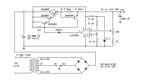
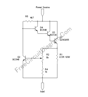
This variable-regulated power supply operates within a voltage range of 3V to 24V, adjustable from 3V to 25V, and is limited to a maximum current of 2A. The current limit can be increased to 3A or more by selecting...
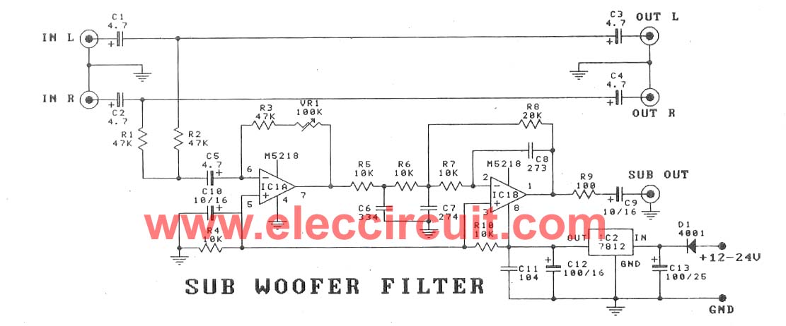
This subwoofer filter set is suitable for use with a high-quality car audio system. The circuit is designed to operate with a 12-volt DC power supply. The subwoofer filter set serves as an essential component in enhancing the audio experience...
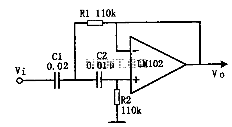
This document presents an active low-pass filter circuit with a cut-off frequency (fc) of 10 kHz. The circuit allows for various values for the ratios of resistors R1 and R2, as well as capacitors C1 and C2. Specifically, it...
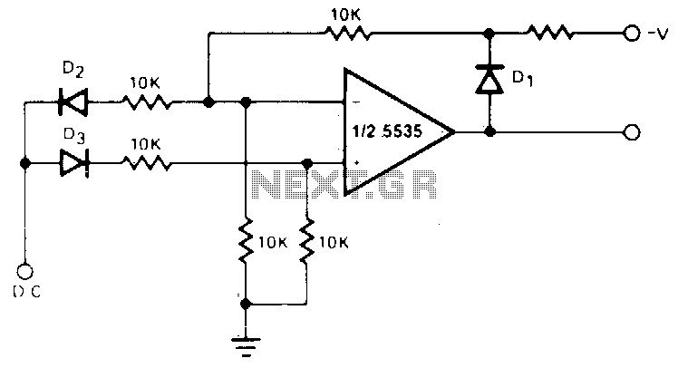
The circuit generates a positive output voltage for either polarity of input. For positive signals, it functions as a non-inverting amplifier, while for negative signals, it operates as an inverting amplifier. The accuracy is poor for input voltages under...
This circuit provides automatic current limiting up to 8.4 A. Unlike current limiters that use only a resistor, this current limiting circuit does not drop the voltage significantly or keeps the voltage drop to a minimum until a specific...
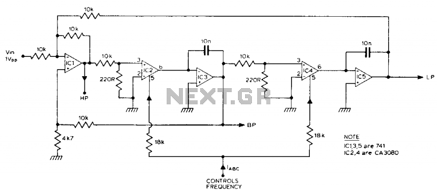
The filter generates three outputs: high-pass, bandpass, and low-pass. The frequency is linearly proportional to the gain of two integrators. Two CA3080 operational amplifiers (IC2, IC4) provide variable gain, with the resonant frequency being proportional to the current. Using...