
Advanced LED Temperature Indicator

The LED display temperature indicator is designed to provide a clear visual representation of temperature readings. The circuit typically includes a temperature sensor, such as a thermistor or an LM35 temperature sensor, which converts temperature into an electrical signal. This signal is then processed by a voltage-to-frequency converter, which transforms the voltage output from the sensor into a frequency signal proportional to the temperature.
The frequency output can be fed into a microcontroller or a frequency counter that interprets the signal and drives an LED display, allowing users to read the temperature in real-time. Additional components may include resistors, capacitors, and a power supply unit to ensure stable operation of the circuit.
In terms of assembly, the circuit can be constructed on a breadboard for prototyping, with careful consideration given to the layout to minimize noise and interference. Proper calibration of the system is essential to ensure accurate temperature readings, which may involve adjusting the V/F converter settings based on the characteristics of the chosen temperature sensor.
This project serves as an educational tool for understanding the principles of temperature measurement and digital display technology, making it suitable for both hobbyists and students in electronics.this verified project provide idea, circuit and working of the system LED display temperature indicator. Digital temperature indicator.using V/F converter.various electronics project. 🔗 External reference
Related Circuits

In this project, eight LEDs are connected to PORT B of a PIC microcontroller. A push-button switch is also connected to bit 0 of PORT A using a pull-up resistor. When the switch is pressed, the LEDs scroll to...
As a keen cyclist I am always looking for ways to be seen at night. I wanted something that was a novelty and would catch the motorists eye. So looking around at my fellow cyclists rear lights, I came...
This circuit diagram represents a radio-controlled system, commonly used in toy car applications for children. The circuit consists of two main parts: the transmitter and the receiver. The transmitter generates radio signals using an oscillator circuit formed by transistor...

The LED Metronome is a contemporary version of a traditional device that is essential for music teachers, students, and composers. This circuit employs 12 LEDs to replicate the swinging motion of a pendulum, along with a speaker connected to...

A four-channel DMX512 controlled ringer. The Mk 3 will also incorporate a ringing supply generator, making it reproducible by those without access to the BT ringing supply Number 7. The ringer is microprocessor-controlled, utilizing a Parallax Propeller-based chip, specifically...
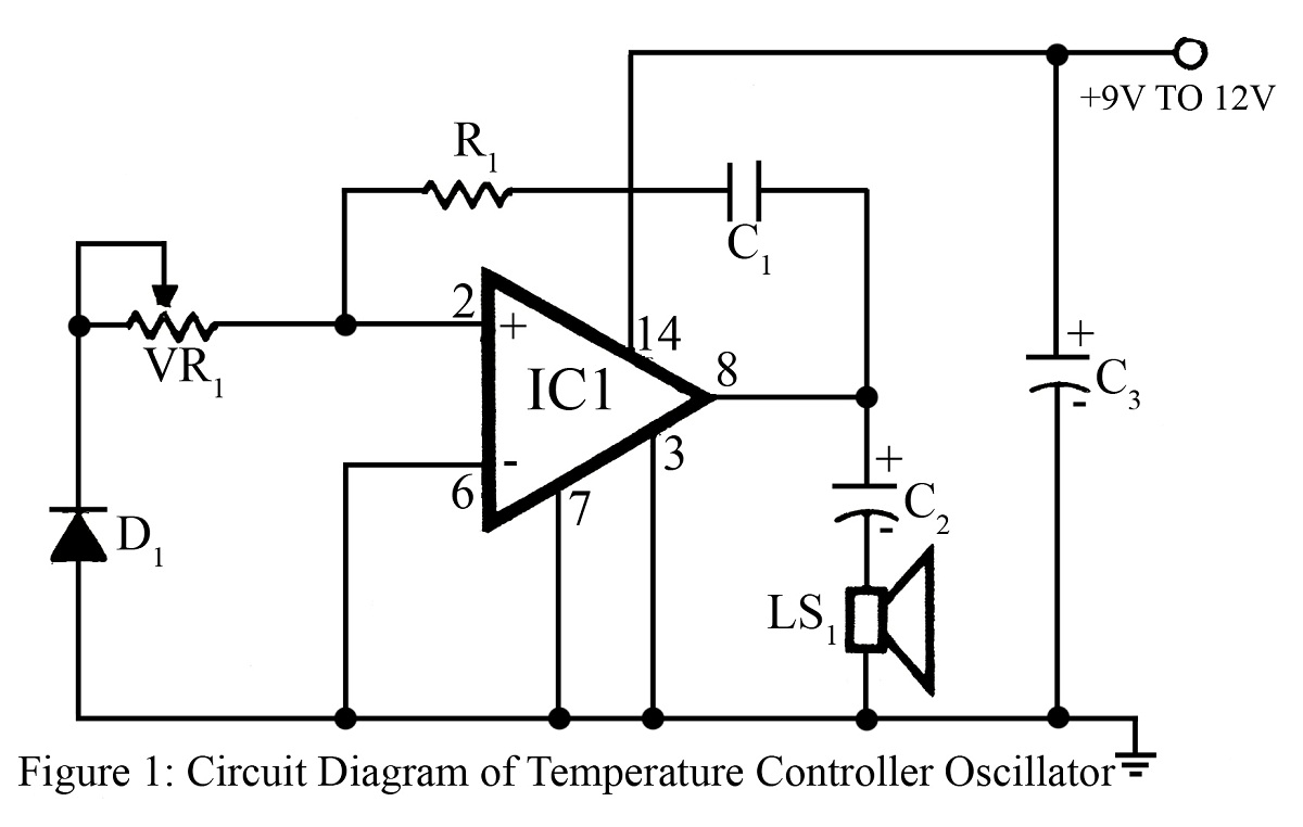
The output frequency or tone of this oscillator circuit varies with the temperature at which the input germanium diode is maintained. The reverse resistance of D1 ranges from 500 ohms to 10 k ohms when the temperature fluctuates between...