
Advances in Measurement & Sensor Tech

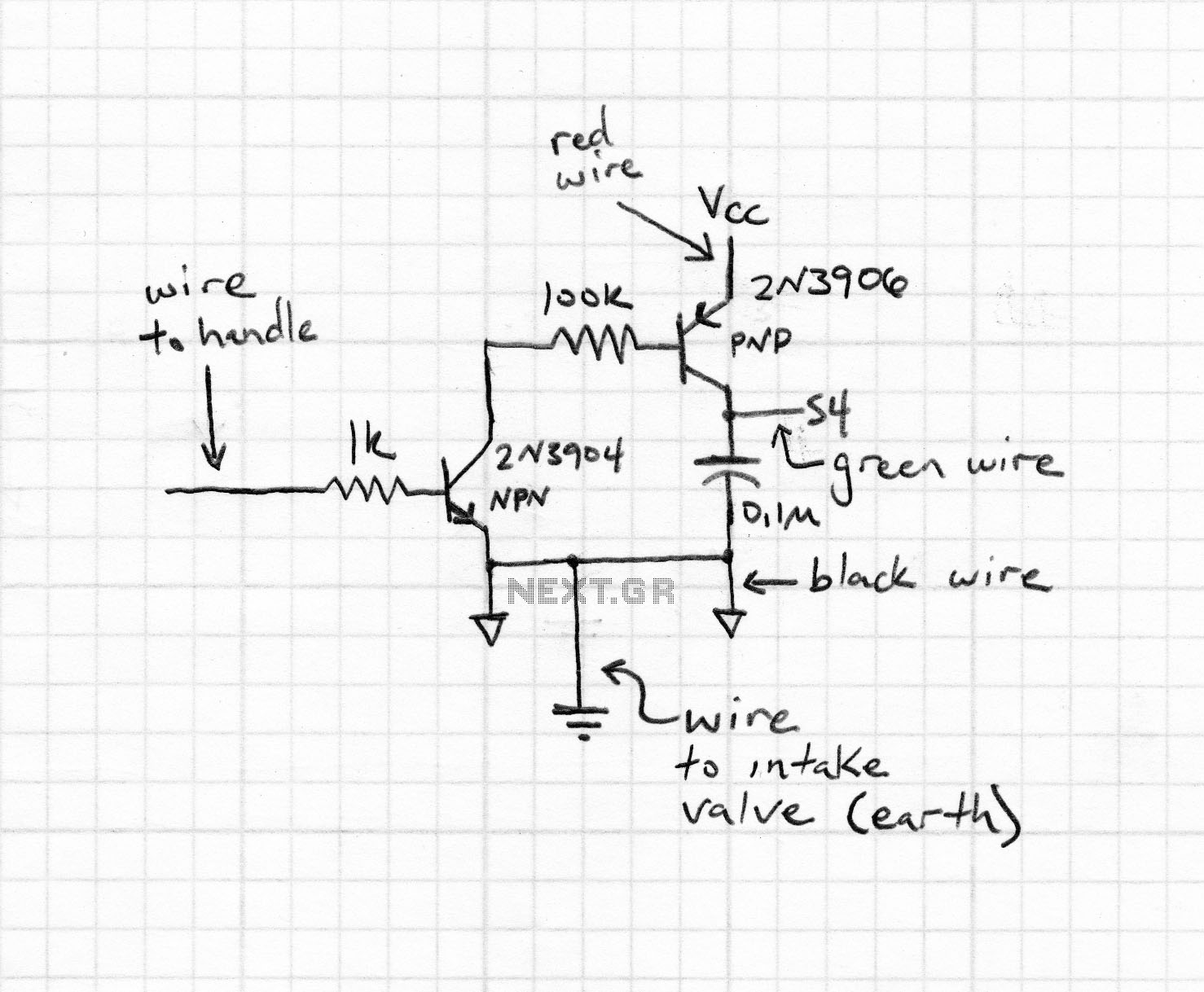
The articles presented in this issue delve into innovative embedded design projects that incorporate sensors and measurement techniques. The multilevel audible logical probe designed by Petrov showcases a practical approach to troubleshooting digital circuits. By providing four distinct input levels, this probe allows engineers to diagnose issues more efficiently. The audible tones serve as immediate feedback, enabling rapid identification of circuit faults, which is crucial in complex digital systems where multiple signals may be present.
Oppenheim's exploration of touch sensors highlights their versatility and potential to enhance accessibility in electronic devices. By integrating capacitive touch sensors, users can interact with devices in a tactile manner, making technology more accessible for individuals with visual impairments. This design not only emphasizes user experience but also illustrates how simple components can be utilized to create meaningful applications.
The menU system tested on the mbed processor exemplifies a straightforward yet effective design strategy. The use of four buttons to navigate the menu system simplifies user interaction, while the alphanumeric LCD provides clear visual feedback. The alternative method of connecting to a PC via the USB-to-serial port offers flexibility, allowing for remote control and monitoring of the menu system. This dual approach caters to different user preferences and enhances the overall functionality of the design, making it suitable for various applications in embedded systems.In this issue, we feature articles on a variety of measurement-and sensor-related embedded design projects. I encourage you to try similar projects and share your results with our editors. Starting on page 14, Petre Tzvetanov Petrov describes a multilevel audible logical probe design. Petrov states that when working with digital systems “it is good to have a logical probe with at least four levels in order to more rapidly find the node in the circuit where things are going wrong.” His low-cost audible logical probe indicates four input levels, and there’s an audible tone for each input level.
Matt Oppenheim explains how to use touch sensors to trigger audio tags on electronic devices (p. 20). His design is intended to help visually impaired users. But you can use a few capacitive-touch sensors with an Android device to create the application of your choice. The design used to test the menU system on the mbed processor was intentionally as simple as possible. Four buttons drive the menu system and an alphanumeric LCD is used to display the menu. Alternatively, one can use the mbed’s USB-to-serial port to connect with a terminal emulator running on a PC to both display and control the menu system.
🔗 External reference
Related Circuits
The Voice Changer features two distinct inputs: a microphone and switches. It processes the input signal and sends it to an operational amplifier (OpAmp) for amplification before outputting to a speaker. The output signal's frequency is modified based on...
The PCD3360 is a CMOS integrated circuit designed to replace the electro-mechanical bell in telephone sets. It meets most postal requirements, featuring selectable output tone sequences and input ringer frequencies. The circuit provides output signals suitable for driving a...
This circuit consists of an infrared phototransistor and an infrared LED. The transducer operates on the principle of light reflection, specifically infrared light. The skin serves as a reflective surface for the infrared light, and the density of blood...
This two-part article explains the utilization of a simple voltage divider circuit incorporating a thermistor to obtain high-accuracy temperature readings across a wide range of measurements. The first part focuses on the circuit design and explores various methods for...
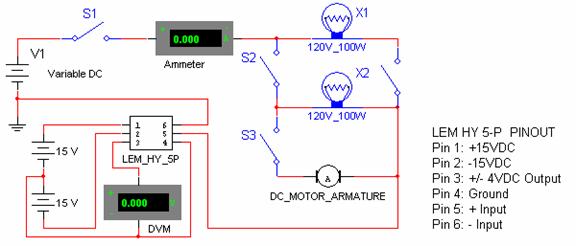
Connect the negative side of the positive supply to the positive side of the negative supply to create a ±15 VDC. This junction serves as the ground for the transducer, ensuring a balanced voltage. Continue the experiment by switching...
The following circuit illustrates an Ultrasonic Sensor Circuit Diagram. This circuit is based on the MAX232 IC. Features include a quiescent current of 150mA. The Ultrasonic Sensor Circuit utilizes the MAX232 integrated circuit, which is primarily designed for converting signals...