
Ultrasonic SensorCircuit Based On The MAX232 IC

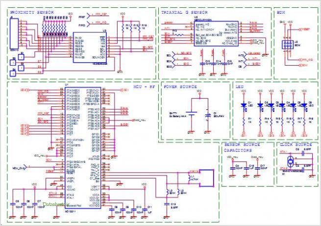
The Ultrasonic Sensor Circuit utilizes the MAX232 integrated circuit, which is primarily designed for converting signals from a TTL level to RS-232 level and vice versa. This is essential in applications where ultrasonic sensors require communication with microcontrollers or other devices that operate at different voltage levels.
The circuit typically includes an ultrasonic transducer, which emits sound waves at a frequency above the audible range. When these sound waves encounter an object, they are reflected back to the sensor. The time taken for the echo to return is measured, allowing for distance calculation to the object.
In addition to the MAX232, the circuit may incorporate additional components such as resistors, capacitors, and diodes to ensure proper signal conditioning and power supply regulation. The quiescent current of 150mA indicates that the circuit is designed to operate efficiently, minimizing power consumption during idle states.
The output from the MAX232 can be connected to a microcontroller, which processes the received signal, calculates the distance based on the time delay of the echo, and can subsequently control other devices or display the results. This circuit is widely used in applications such as obstacle detection, distance measurement, and automation systems.The following circuit shows about Ultrasonic Sensor Circuit Diagram. This circuit based on the MAX232 IC. Features: 150mA quiescent current, .. 🔗 External reference
Related Circuits
Many of today's high-performance FPGAs, microprocessors, DSPs, and industrial/embedded subsystems require sequencing of the input power PS10 and PS11. Historically, this has been achieved through: i) discrete methods using comparators, references, and RC circuits; ii) expensive programmable controllers; or...
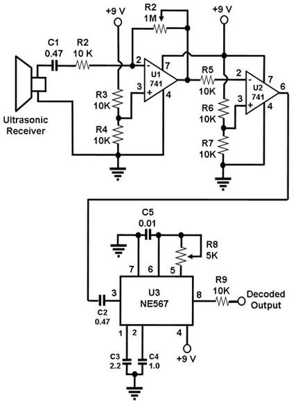
The ultrasonic receiver utilized in this circuit is specifically designed to vibrate optimally at a frequency of approximately 40 kHz. Consequently, the transmitter associated with this receiver must also emit waves at 40 kHz. When these waves interact with...
The following circuit illustrates a simple stepper motor controller circuit diagram. This circuit is based on the 7404 integrated circuit. Features include suitable heat dissipation. The simple stepper motor controller circuit utilizes the 7404 hex inverter IC to control the...
The WWVB signal is transmitted as a 60 kHz carrier wave that is amplitude modulated with a time code frame updated once every minute. The data rate is one bit per second. The data frame includes synchronization bits, calendar...
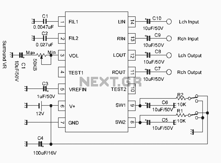
The NJM2701 3D surround sound audio processor integrated circuit can be designed into a very simple 3D surround sound system. The NJM2701 reproduces 3D surround sound using only two speakers and is suitable for various audio applications, including micro-components,...
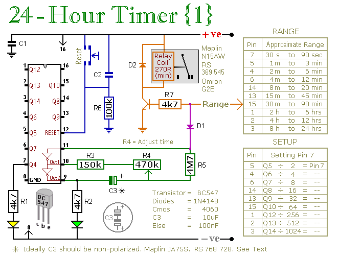
A pair of multi-range timers capable of timing periods up to 24 hours and beyond. Both versions are fundamentally similar, with the primary distinction being that Version 1 energizes the relay when the time expires, while Version 2 de-energizes...