
Air humidity measuring circuit 2

The humidity alarm system is designed to monitor and respond to humidity levels in various environments. The core of the system is the pA741 operational amplifier, which provides the necessary signal conditioning for the humidity sensor. The MS01 humidity sensor, which operates on the principle of resistance change with moisture absorption, serves as the primary detection element.
When the humidity level rises above the defined threshold, the resistance of the sensor decreases, resulting in a voltage change at the input of the pA741. This change is amplified and processed to drive relay KA. The relay, upon activation, completes the circuit for the alarm, alerting users to the high humidity condition.
To fine-tune the system, the adjustment potentiometer RP is incorporated into the circuit. This component allows the user to set the desired humidity threshold, providing flexibility for different applications and environments. The potentiometer is connected to a voltage divider configuration, which adjusts the reference voltage fed to the pA741, thereby determining the activation point for the relay.
The entire circuit can be powered by a standard DC power supply, and it is essential to ensure that all components are rated for the operational voltages and currents to avoid damage. Proper layout and grounding practices should be followed in the schematic design to minimize noise and ensure reliable operation of the humidity alarm system. Based integrated circuits and relays KA constitute humidity alarm value it uses pA741 circuit. MS01 using a wet-type humidity resistance element as a probe. When the humidity e xceeds a predetermined value, Az 6 feet high, relay KA pull, turn the alarm circuit. Adjustment potentiometer RP, may decide the upper limit of humidity.
Related Circuits
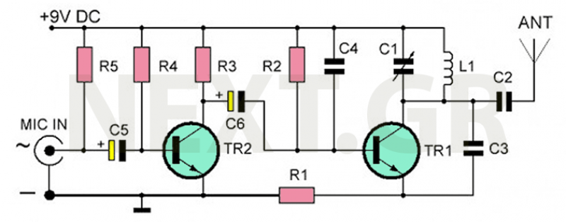
The recommended transmitter is straightforward to construct and suitable for beginners. Despite its simple design and compact size, it delivers remarkable performance. It operates for 12-15 hours on a 9-volt battery and has a transmission range of 100 to...
This is an intercom circuit that utilizes the LM380 as the audio amplifier and two transistors for the microphone preamplifier. The sound quality is sufficiently good while maintaining a low construction cost. The circuit comprises two identical intercom units,...
The circuit illustrated includes a sound transducer sensing switch, an electrical light control switch, an SCR control circuit, a vocal music circuit, and an AC step-down rectifier circuit. The circuit comprises several interconnected components that serve distinct functions, allowing for...
This circuit allows the use of an inexpensive loudspeaker as a microphone. Sound waves that reach the speaker cone cause fluctuations in the voice coil. The movement of the voice coil within the speaker's magnetic field generates a small...
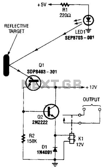
A reflector isolator detects the presence of an object by bouncing light off of it. This technique is useful in circuits that detect when an object is close enough to the sensor. A reflector isolator is a type of optical...
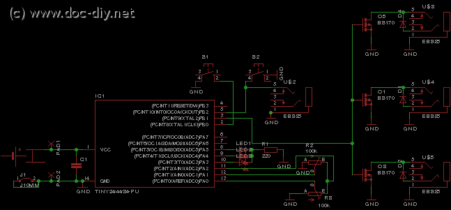
This article outlines the construction of a simple microcontroller-based delay circuit designed for photographic applications such as drop or high-speed photography. It can control the trigger lag of cameras and flash units, generate periodic trigger pulses, or manage magnetic...