
delay circuit for photography

The circuit design incorporates the ATtiny24 microcontroller, which serves as the core processing unit. The microcontroller's pin configuration allows for the integration of input and output interfaces, facilitating seamless communication with external devices. The three output channels enable simultaneous control of multiple photographic devices, enhancing versatility in various photographic scenarios.
The delay circuit employs two potentiometers for fine-tuning the delay settings, ensuring precise control over timing adjustments. The coarse potentiometer allows for broad adjustments, while the fine potentiometer fine-tunes the settings, providing flexibility for users in different lighting conditions and photographic techniques.
The EEPROM functionality ensures that the last used settings are retained, which is crucial for photographers who may frequently switch the device on and off. This feature enhances usability and allows for quick adjustments without the need for recalibration each time the circuit is powered.
The manual trigger button is designed to facilitate testing and adjustments without triggering the camera or flash unit, allowing photographers to make necessary changes to lighting or timing before capturing the shot. The ability to simulate trigger events is particularly useful during setup.
The ability to switch between delay and pulse width modes offers additional functionality, catering to specific photographic techniques that require precise timing control. This adaptability makes the circuit suitable for a wide range of applications, from high-speed photography to controlled lighting setups.
Overall, this microcontroller-based delay circuit is a valuable tool for photographers, offering a combination of simplicity, functionality, and adaptability to meet various photographic needs.This article describes how to build a simple uC based delay circuit for photographic applications like drop or high speed photography. It can be used to control the trigger lag of cameras and flash units, generate a periodic trigger pulse or even control magnetic valves.
The input and the three outputs of the circuit use standard 3. 5 mm stereo jac k connectors, so the delay element can be looped easily into your existing trigger circuitry like the SmaTrig for example. Cascading multiple delay devices into more complex circuits is easily done. As simplicity was an important design goal, there is no text display or a sophisticated analog input stage.
All resources to build a copy of the delay are provided below in the Download section. A short press of the on/off button switches the circuit on and off. By holding the on/off button down while switching on you can cycle through the three time ranges indicated by the LEDs. The chosen operating range is saved in the EEPROM so the uC will remember the last setting after switching off or even removing the battery.
Directly after programming the AVR your delay will work as described in this section. The delay time is set by two potentiometers. The left one is used for the coarse time setting (0-100% of the chosen range), the right one allows fine tuning (0-10% of the chosen range) of the delay time. Both knobs turned to the maximum will result in 110% delay time (1. 1 s, . ). The functions of the wheels are: The coarse/fine solution proved to be very convenient in practical use (dark room).
For drop photography, the absence of a display turned out to be unproblematic, because you keep your eyes on the drop and not the delay while adjusting the time. The manual trigger button allows to simulate a trigger event and is useful for lighting adjustment or general testing.
It just shortens out the input contacts. The duration of the trigger pulse in this mode is always 0. 35 s. The minimum lag of the circuit in the green mode for both potentiometers set to 0 is about 12 us (microseconds). Use this setting if you like to use the delay circuit just as a repeater to fire for example three different flashes from one source.
The lag will be negligible in most cases. There are applications where it would be useful to have control over the duration of the trigger pulse width. Examples are bulb mode shots or the generation of drops with magnetic valves. For such special cases the delay circuit can be switched to a different mode, where the right rotary knob changes it`s function form fine tuning the delay time to controlling the trigger pulse duration.
The resulting functions and times are: To toggle to this operating mode press the on/off button for more than 6 s while switching on the device. The LED will cycle through the ranges twice and start to cycle faster. If the delay / pulsewidth mode is enabled, the LEDs will blink once after switching on. Follow the same procedure to toggle back to the standard coarse/fine mode. Short-circuiting the input permanently (connect tip and shaft in stereo jack plug or block the trigger button) will result in periodic self-triggering.
This way a simple interval timer can be realised. The interval period will be the sum of the delay time, the trigger pulse duration and the internal re-trigger blockage time of 150 ms. Accordingly the maximum achievable frequency will be about 6. 6 Hz. For some slow processes the delay range of 1 s might be too short. By connecting pin 6 and 7 of the uC together (see marking in image above) the time ranges are increased by a factor of 100.
Correspondingly they change to: 100 s, 10 s, 1 s. All other changes must be done in the AVR C code. Note that the pins are checked once when the circuit is switched on. The circuit is based on the ATtiny24 AVR by Atmel. With its 14 pins the controller is a good compromise between the very small Tinys and the bigger ATmega types. The 🔗 External reference
Related Circuits
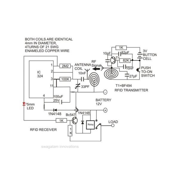
Constructing an RFID access control circuit at home and witnessing its functionality can be a remarkable experience. While the circuit may not be considered high-tech, its low cost combined with the satisfactory results achieved demonstrates a significant level of...
This remote telephone bell ringer enables the use of a large and loud external bell instead of or in addition to the built-in ringer found in most modern telephones. It is particularly suitable for large outdoor areas, noisy shops,...
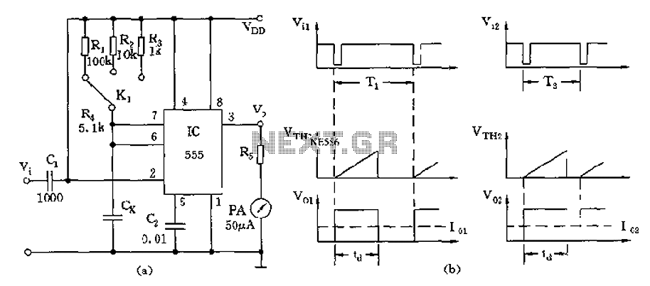
The circuit utilizes a 555 timer along with timing resistors R1 to R3 and a measured capacitance Cx to create a capacitance meter. The principle of capacitance measurement in a one-shot circuit is based on the relationship between the...
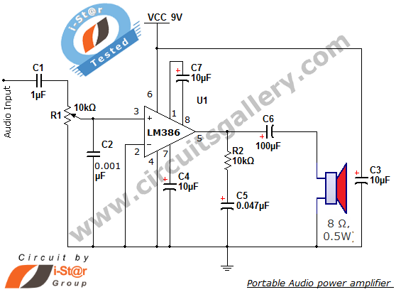
The i-St@r presents a simple mini audio amplifier circuit schematic utilizing the LM386 low voltage audio power amplifier IC. This circuit is designed to power medium-sized speakers from a music player that typically drives only earphones (LM386 headphone). The...
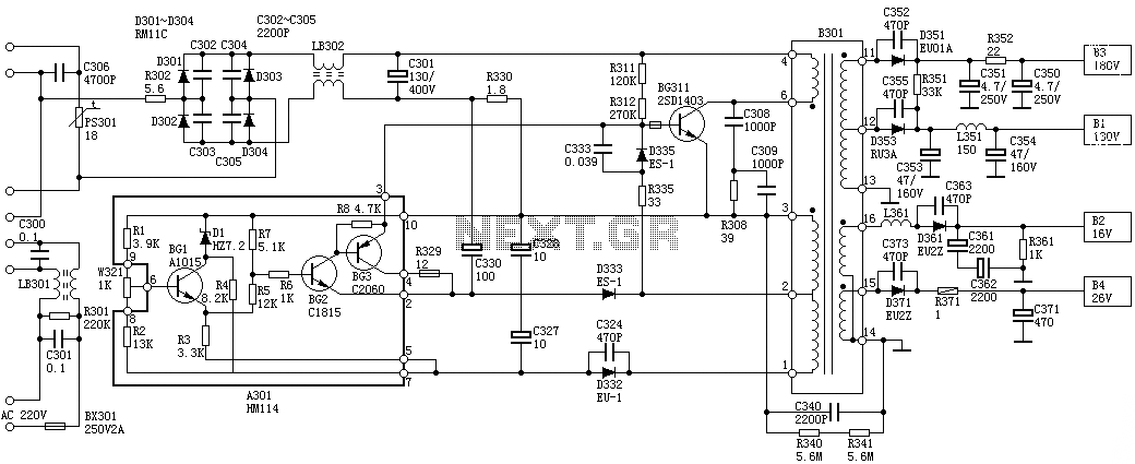
Oscillation: The positive terminal voltage of C310 is approximately 300V. The resistors R311 and R312 are connected to the switch BG311 at the B pole, while the B301 winding via the switching transformer (4) and (6) is connected to...
A simple audio amplifier with a 10 Vpp output designed for use with the AD633 ring modulation chip. The datasheet for the chip is available, and the circuit will utilize the XR2206 function generator IC for the modulation input....