
All in one Remote using Arduino

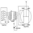
The project evolved into a comprehensive remote that includes features such as RF wireless control, an intervalometer, a real-time clock, and interfaces for external triggers. However, as suggestions for additional features poured in from forum members, the project outgrew the capabilities of the PICAXE 18X. A month later, the individual opted for the PICAXE 28X1, which offers more program memory. Ultimately, the ideal choice became the Arduino ATmega168 processor, a 28-pin chip with ample I/O and 16k of program RAM, supported by a free development system for easy programming.
The all-in-one remote is a compact photographic accessory designed for convenience and versatility, suitable for various photography settings. It incorporates a wired remote, wireless remote, camera power supply, intervalometer, and an interface for devices like pressure-sensitive pads and trip wires. The intervalometer allows for customizable pause durations between shots, ranging from 0 seconds to nearly 1000 hours, and can be programmed for scheduled operations. This feature is particularly useful for long-term documentation tasks, such as capturing images of construction progress at specific intervals.
The unit can be powered by a self-contained 9-volt battery or an external 12-volt power supply, making it adaptable for different scenarios. While primarily designed for the Panasonic FZ30, the remote can be modified to work with other digital cameras that support wired remote control. Instructions for compatibility with Canon prosumer DSLRs are also provided, along with a personality plug for easy output circuit configuration for various camera models.
The project is intended as a build-it-yourself endeavor, allowing hobbyists to utilize readily available components and customize the design as needed. While the creator has only tested the unit on a breadboard and does not plan to manufacture a circuit board or kits, experienced hobbyists are encouraged to undertake the project. Collaboration with others interested in producing circuit boards or kits is welcomed, although commercial sales of the design are prohibited.
This remote control system serves as an innovative and cost-effective solution for photographers seeking enhanced control over their camera functions, enabling a range of creative possibilities in both field and studio environments.August, 2007One of my other hobbies is photography, and, about a year ago, I purchased a new digicam a Panasonic FZ30. I joined the Panasonic forum on the dpreview site. One of the posters, a programmer and electronic hobbyist, designed a nifty wireless remote using a very inexpensive RF transmitter/receiver combination that he found on eBay.
After he`d perfected that, he began designing an interval timer using a Radio Shack egg timer. At the time, I had just discovered the Picaxe 18X microcontroller. I realized that the PICAXE might make a good vehicle to power such photographic accessories, and that some sort of do everything remote might be a good project to learn how to use the PICAXE. Even better, the Picaxe is programmed in a very simple form of BASIC. Programs can be downloaded to the processor over a serial link from your computer ” no programmer is required.
And the development system is a free download. In this case, a Picaxe is an ideal vehicle for gizmo design, since anyone can duplicate a project designed with one of these chips, and many can do design modifications or original designs with them. So, with a good deal of discussion with Bryan (linuxworks on dpreview), I conceived the remote described herein, one combining an RF wireless remote, intervalometer, real-time clock, externally-triggered remote, wired remote, and a camera power supply.
Unfortunately, during the design phase, I received more and more suggestions for features from folks in the forum. Soon, my little Picaxe proof-of-concept project outgrew anything that could possibly be implemented on the little Picaxe.
I decided, about a month ago, to have another try at this project. I knew that this was too much for the Picaxe 18X, but RevEd had recently introduced the Picaxe 28X1, having much more program memory than the 18X. So I gave the 28X1 a try. I finally found the right processor in the Arduino version of the ATmega168 processor. This is a 28 pin chip, with lots of I/O, and 16k of program RAM. And, like the Picaxe, the Arduino is supported by a free development system that can download a program to the processor from your PC without requiring any dedicated programming hardware.
It proved to be the ideal processor for this project. The All-in-one remote has been designed as a versatile, portable photographic accessory that you can tuck in your camera bag. It combines a number of useful features that you will provide capabilities that you`ll find both useful and fun during your field, home, or perhaps even studio photography.
In one box, you`ll find a wired remote, a wireless remote, a power supply for your camera, a versatile intervalometer, and an interface to devices such as pressure-sensitive pads, trip wires, etc, that can take a picture when your subject trips the trigger device. You can program the intervalometer to pause between pictures anywhere between 0 seconds and almost 1000 hours.
It will stop taking pictures after the number of shots you specify so you won`t overfill your digicam`s memory card capacity. You can also program the intervalometer for scheduled operation, automatically starting and stopping at specified times on specified days.
Let`s say you`ve been hired to document the history and progress of a construction project. You`d like to lock a camera in place, then take a picture of the construction site every 30 minutes between 7 AM and 4:30 pm, on Mondays through Fridays. The AI-1 is just what you need for this job, or any other long-term photography task. The unit is powered by a self-contained 9 volt battery, or can be powered by an external 12 volt wall wart power supply or even a 12-volt sealed lead-acid battery pack.
In effect, this is an accessory that`s easy for you to build, following instructions on this page, that won`t cost you a fortune, but will provide lots of features you can use to improve your photography. And it all tucks into your gadget bag. Although I`ve designed the remote for the Panasonic FZ30, this project can be adapted to almost any digital camera that can be controlled by some sort of wired remote.
Instructions are provided to drive Canon prosumer dSLR`s as well as the Panasonic FZ line. The design is readily adaptable to other cameras, too, by means of a personality plug that can easily configure the output circuit for different cameras. Right now, I only have the wired remote details for Panasonic and Canon cameras. As I proceed, I`ll try to find out how wired remotes work on other cameras, and will update the appropriate information.
Any help would be greatly appreciated. (If you improve the design, please publish your results and let me know what you`re doing. I`ll be happy to link to your project page. Likewise if you just build one of these units as designed, I`ll help you brag, and be happy to post a photo (or more) on this page. ) I`ve only constructed and tested this unit on a breadboard. I`m not certain that I`ll ever build it into a box, since my style of photography doesn`t really demand a unit like this.
(My style of photography could, however, make good use of a computerized az-el platform, so something like that might be my next photography project ) During a previous attempt at this project, I had a number of enquiries for circuit boards. At this time, I have no intention (and very dubious skills) of designing a circuit board. I see too many problems accommodating different parts, housings, etc. I`d have to specify a parts list very tightly in order to accommodate a single-design circuit board, then establish and maintain a supply chain.
That`s virtually an impossible task for an individual. Even if I did decide to have some boards made, I`d have to invest quite a bit of money up front to obtain a supply of boards for an uncertain market. And, since I don`t have access to the infrastructure to supply either parts kits or finished units, those are out of the question at this time, too.
So this is a build-it-yourself project. I`ve left the design loose enough to accomodate parts that you might have on hand, or be able to purchase easily, and where possible, I`ve allowed for reasonable parts substitution. If you`re an experienced hobbyist, you should be able to successfully complete this project. However, if any of my readers would like to have a batch of boards made for this project, or furnish kits to hobbyists, you have my blessing.
(If you do a nice mechanical design and kit it well, something outside my skill set, I would be very interested in buying a kit from you. ) If you want to build and market this as a commercial product, that`s a no-no. 🔗 External reference
Related Circuits
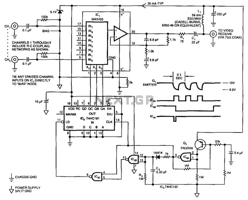
This single-cable system transmits composite video (NTSC, PAL, or SECAM), power, and channel selection signals. The interface end of the circuit delivers 10 V down the cable, pulses the supply voltage to transmit channel-change commands, and buffers the received...
This application note outlines the transmission of I²S audio data streams between two audio components using a single shielded twisted-pair (STP) wire, employing the MAX9205 10-bit LVDS serializer and the MAX9206 10-bit LVDS deserializer. Low-voltage differential signaling (LVDS) serves...
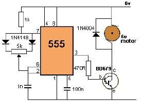
This project utilizes a 555 timer to control the speed of a 6-volt DC motor. Speed adjustment is achieved by rotating a 50 kΩ potentiometer either to the left or right. The circuit employs the 555 timer in astable mode,...
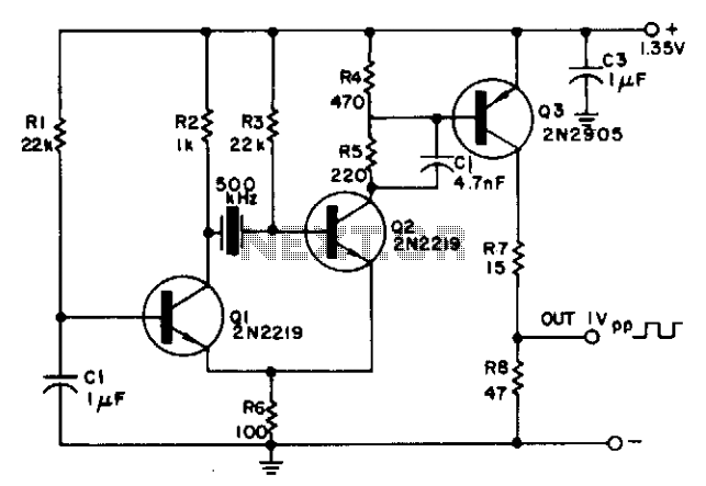
The circuit is powered by a single 1.35 V mercury cell and provides a 1 V square-wave output. The crystal acts as a tuned circuit between transistors Q1 and Q2, which are connected in a common-emitter configuration. Positive feedback...
The simplest method to drive a stepper motor with a lower current rating is by utilizing the ULN2003. The ULN2003 consists of seven Darlington transistors and can handle up to 500mA per channel, with an internal voltage drop of...
The objective is to enhance information transmission through the use of articles. Please contact us via email at [email protected] within 15 days if there are any issues related to article content, copyright, or other concerns. Prompt action will be...